
A cylindrical antenna helical laser pattern device and method thereof

A laser and antenna technology, applied in the field of cylindrical antenna spiral laser pattern technology, to achieve the effect of simple and easy operation of the fixture

Active Publication Date: 2017-09-05
SHANGHAI RADIATE COMM ELECTRONICS
View PDF6 Cites 0 Cited by
  • Summary
  • Abstract
  • Description
  • Claims
  • Application Information

AI Technical Summary

Problems solved by technology

[0010] In order to solve the existing problems of laser stripes of such products, it is truly integrated, and to ensure that the spiral stripes of the product are truly uniform and the laser effect is consistent, and the product performance and function truly meet the actual requirements of antenna RF (radio frequency) testing.

Method used


Image

  • A cylindrical antenna helical laser pattern device and method thereof
  • A cylindrical antenna helical laser pattern device and method thereof
  • A cylindrical antenna helical laser pattern device and method thereof

Examples


Embodiment example

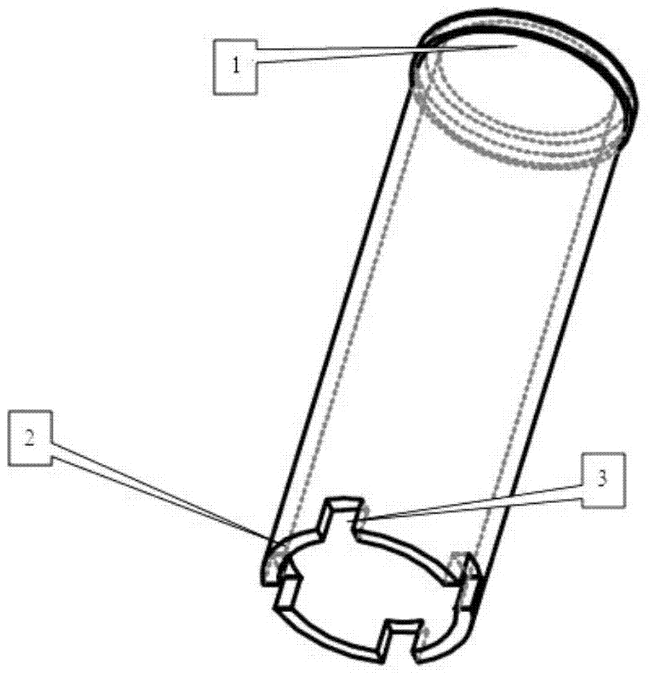
[0057] like Figure 1~3 As shown, the raw material will be fixed on the profiling jig. The profiling design makes the jig completely match the raw material and completely fix the raw material. The raw material directly depends on or is synchronized with the rotation of the profiling jig in the longitudinal rotation. The fixed raw material buckle design is that the raw material is firmly fixed on the profiling jig to prevent the raw material from moving or detaching from the profiling jig during the rotation movement , to ensure the normal operation of the work. Fix the profiling jig on the large chassis of the motor jig by connecting the fixing block to ensure that the profiling jig is connected to the private server motor and rotates concentrically. Before normal work, we use the convex part of the horizontal cylindrical upper surface as the plane point of the laser focal length to make and design the corresponding laser engraving program, including the graphic size of the r...


PUM


Abstract

The invention relates to a cylindrical antenna spiral laser line device and a method thereof. The cylindrical antenna spiral laser line device comprises a raw material clamping and fixing jig and a laser bottom plate mechanism with a servo motor. The laser bottom plate mechanism with the servo motor is composed of a base, a large rotating shaft, a large bottom plate, a jig fixing base, a swing arm servo motor and a rotating servo motor. The raw material clamping and fixing jig is composed of a fixed raw material profiling jig block, a profiling jig block body and a profiling jig connecting and fixing block. By means of the design, integrated forming of the spiral antenna design is achieved, tedious steps of other design are omitted, waste caused in other design is saved, the overall time of the technological process is saved, stability of the whole process forming is greatly improved, and product efficiency and quality are greatly improved.

Description

[0001] [technical field] [0002] The invention relates to the technical field of cylindrical antenna spiral laser texture technology, in particular to a cylindrical antenna spiral laser texture device and a method thereof. [0003] [Background technique] [0004] In the production line production process, the general LDS (Laser-Direct-Structuring through laser direct structuring to achieve selective metallization on the molded carrier) process is limited to segmented on a plane or a similar plane. Various small areas of laser engraving, various straight line stripes, circular stripes, squares, parallelograms and other images can only form fixed graphic laser stripes on a certain plane or similar plane. It is very difficult for some products to form an overall perfect and uniform laser pattern on the cylindrical convex surface. [0005] First of all, the focal length and depth of laser are limited. In actual operation, only a small area of ​​the convex part of the cylindrical ...

Claims


Application Information

Patent Timeline
Patent Type & Authority Patents(China)
IPC IPC(8): B23K26/362B23K26/70B23K37/047B23K101/36
CPCB23K37/047B23K2101/36
Inventor 李峰浪杨宏沈程桂
Owner SHANGHAI RADIATE COMM ELECTRONICS
Learn More