positioning clamping mechanism

A technology for positioning, clamping and resetting parts, applied in positioning devices, clamping, metal processing mechanical parts, etc., can solve the problems of workpiece damage, affecting production efficiency, cumbersome steps, etc., to achieve accurate repeated positioning, high production efficiency, and operation. Quick and easy effects

Inactive Publication Date: 2017-09-12
SHENZHEN ULMT TECH CO LTD
View PDF9 Cites 0 Cited by
  • Summary
  • Abstract
  • Description
  • Claims
  • Application Information

AI Technical Summary

Problems solved by technology

[0004] 1) The positioning accuracy is not high
Even though the profiling surface has a high degree of fit with the workpiece, since multiple quick clamps act on the workpiece in sequence, during the clamping process, it is easy to cause the workpiece to shift because one side is fixed and the other is in a free state, resulting in the positioning of the final single product The accuracy is not high, and the repeat positioning accuracy is not high (in the present invention, "repeat positioning accuracy" is the consistent degree of continuous results obtained by processing a batch of parts under the same conditions)
[0005] 2) Damage to the workpiece
The workpiece needs to withstand external forces during the production process, such as grinding, drilling, etc., and is only fixed by quick clamps. When the clamping force is too small, the workpiece is prone to movement, causing the contact surface between the quick clamp fixture and the workpiece to be scratched; if If the clamping force is too large, the thin workpiece is easily deformed due to excessive force
[0006] 3) Multiple quick clips are picked and placed one by one, the steps are cumbersome and affect production efficiency
[0007] With the increasingly strong requirements for automated production, the above-mentioned existing fixtures can no longer meet the production and processing requirements of the product.

Method used


Image

  • positioning clamping mechanism
  • positioning clamping mechanism
  • positioning clamping mechanism

Examples


Embodiment Construction

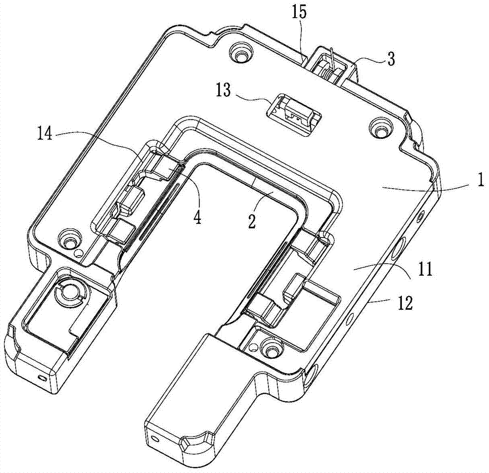
[0056] The invention discloses a positioning and clamping mechanism. The profiling surface is used for positioning, and the buckle is controlled by the buckle switch assembly to perform line contact and fixation on the edge of the workpiece to be processed.

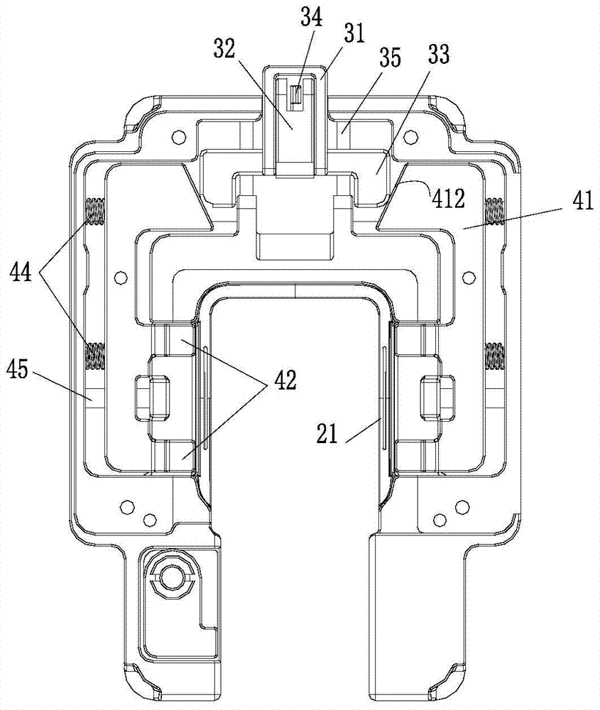
[0057] If the shape of the workpiece to be processed is a regular figure, as in the present invention Figure 5A In the rectangular recessed mobile phone back cover, the buckles can be arranged symmetrically on both sides of the workpiece to be processed. The left and right buckles are controlled by a buckle switch assembly, and the workpiece A to be processed is fixed at the same time.

[0058] For convenience of description, the figure 1 The opening direction of the main body in the figure is called "front", the direction corresponding to the opening is called "back", the left side of the figure is called "left", the right side of the figure is called "right", and the direction of the center of the profiling surface i...


PUM


Abstract

The invention discloses a positioning and clamping mechanism. The positioning and clamping mechanism comprises an annular main body of which the interior is provided with a containing space, profiling faces fixed on the inner ring of the main body, a buckle switch assembly which is located in the containing space and partially stretches out of the main body and buckle parts; each buckle part comprises a buckle part main body, buckle claws extending out of the main body from the buckle part main body to the positions above the profiling faces and a buckle resetting part which is located between the main body and the buckle part main body and makes contact with the main body and the buckle part main body, and an oblique face upwards transiting from outside to inside is adopted as the lower surface of each buckle claw; the buckle switch assembly can drive the buckle part main bodies to compress the buckle resetting parts to enable the buckle claws to be far away from the profiling faces; the buckle resetting parts can push the buckle part main bodies to be close to the profiling faces. The positioning and clamping mechanism is applied to an automatic production line of thin products and can accurately position and fix workpieces to be machined and prevent damage to the workpieces due to clamping.

Description

technical field [0001] The invention relates to a positioning and clamping mechanism applied to an automatic production line, which belongs to the field of mechanical manufacturing. Background technique [0002] In the existing production lines that produce thin products such as mobile phone back cases and watch mirrors, the profiling surface is often used to fix the workpiece with clamps such as quick clamps for processing, such as Figure 8 As shown: the workpiece A' is placed on the profiling surface 20, and the quick clamp 10 is pressed on the upper surface of the workpiece A' from top to bottom, and interacts with the profiling surface 20 below to fix the workpiece A'. [0003] Positioning and clamping workpieces with this fixture structure has the following disadvantages: [0004] 1) The positioning accuracy is not high. Even though the profiling surface has a high degree of fit with the workpiece, since multiple quick clamps act on the workpiece in sequence, during t...

Claims


Application Information

Patent Timeline
Patent Type & Authority Patents(China)
IPC IPC(8): B23Q3/08
CPCB23Q3/065B23Q3/088
Inventor 聂林红
Owner SHENZHEN ULMT TECH CO LTD
Why Eureka
Try Eureka