Spatial three-branch beam string structure footbridge

A pedestrian bridge and space technology, used in bridges, bridge parts, bridge construction and other directions, can solve the problems of serious vibration comfort for pedestrians crossing bridges, low structural stiffness of the string beam, and large deflection acceleration of the main beam, etc., to improve the vibration comfort, The effect of improving the bending moment of inertia and shear stiffness and reducing the local bending moment

Active Publication Date: 2016-04-06
SHANGHAI URBAN CONSTR DESIGN RES INST GRP CO LTD
View PDF6 Cites 5 Cited by
  • Summary
  • Abstract
  • Description
  • Claims
  • Application Information

AI Technical Summary

Problems solved by technology

[0003] However, the tension beam bridge also has disadvantages: the stiffness of the tension beam structure is small, the deflection of the main girder under the action of live load, and the acceleration of the bridge deck under the action of live load excitation force are relatively large
[0004] In particular, when the main girder is a three-pronged girder, the intersection nodes of the main girder are arched upwards, and the plane line of the cables is "concave", if the conventional string beam bridge structure system is adopted, the following problems will exist: 1) The overall stiffness of the structure is relatively The single main girder structure is weakened; 2) The horizontal displacement of the structure under the vertical load is relatively large; 3) The vibration comfort of pedestrians crossing the bridge is more serious

Method used


Image

  • Spatial three-branch beam string structure footbridge
  • Spatial three-branch beam string structure footbridge
  • Spatial three-branch beam string structure footbridge

Examples


Embodiment Construction

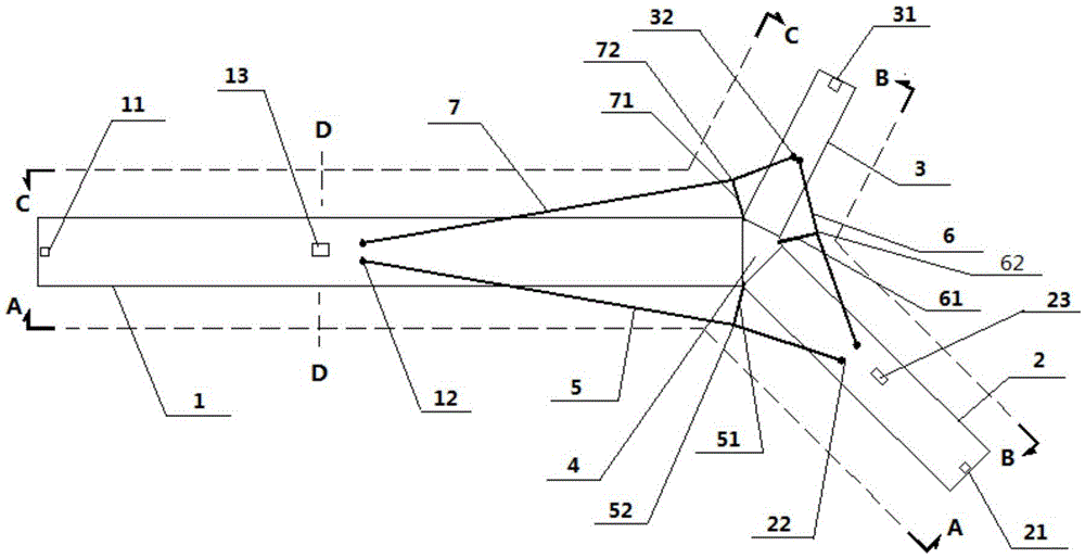
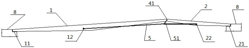
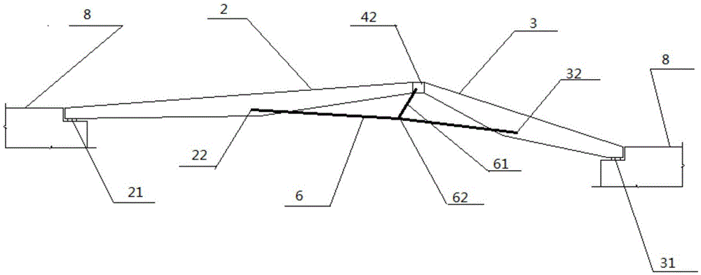
[0027] Such as Figure 1-Figure 4 As shown, a specific embodiment of the space trident string girder pedestrian bridge of the present invention includes a first main girder 1, a second main girder 2 and a third main girder 3, and the first main girder 1, the second main girder 2 and the third main girder One end of the beam 3 is the intersection end, the intersection end of the first main beam 1, the second main beam 2 and the third main beam 3 meet at the intersection node 4, the first main beam 1, the second main beam 2 and the third main beam The other end of 3 is the supporting end, and the supporting ends of the first main beam 12, the second main beam and the third main beam 3 are respectively supported by the first fixed support 11, the second fixed support 21 and the third fixed support 31 In the abutment 8, the first fixed support 11, the second fixed support 21 and the third fixed support 31 are all 7MN fixed supports.

[0028] The fixed support used in this embodim...


PUM


Abstract

The invention discloses a spatial three-branch beam string structure footbridge which comprises a first main beam, a second main beam and a third main beam, wherein one ends of the three main beams are converged on a convergence node, and the other ends of the three main beams are supported on a bridge abutment through fixed supports; a first dragline is arranged between the middle part of the first main beam and the middle part of the second main beam, a second dragline is arranged between the middle part of the second main beam and the middle part of the third main beam, and a third dragline is arranged between the middle part of the third main beam and the middle part of the first main beam; and three anchorage plates are arranged on the side wall of the convergence node, a first connecting rod is arranged between the first anchorage plate and the first dragline, a second connecting rod is arranged between the second anchorage plate and the second dragline, and a third connecting rod is arranged between the third anchorage plate and the third dragline. According to the spatial three-branch beam string structure footbridge disclosed by the invention, the horizontal displacement of the structure under the action of vertical load can be limited, the integral rigidity of the three-branch beam string structure bridge can be increased, the local stress concentration degree of the convergence node of the three main beams can be reduced, and the vibration comfort can be improved when pedestrians cross the bridge.

Description

technical field [0001] The invention relates to the technical field of bridge construction, in particular to a space trident string beam pedestrian bridge. Background technique [0002] Zhangxian girder bridge has the characteristics of clear force and light weight. Its concept was proposed in the 1980s. The structure system of Zhangxian girder bridge is relatively simple, and the main girder (bridge deck system) has a huge volume. The conventional form is simply supported girder with one main girder (single main girder). This structural form is convenient for design, construction and later maintenance. There have been application examples in domestic bridge engineering. [0003] However, the tension beam bridge also has disadvantages: the stiffness of the tension beam structure is small, the deflection of the main girder under the action of live load, and the acceleration of the bridge deck under the action of live load excitation force are relatively large. If the string...

Claims


Application Information

Patent Timeline
Patent Type & Authority Applications(China)
IPC IPC(8): E01D12/00E01D19/04E01D19/00
CPCE01D12/00E01D19/00E01D19/04
Inventor 胡方健何飞汤秋华冯师蓉柳亦春王伟实徐海磊孙琦
Owner SHANGHAI URBAN CONSTR DESIGN RES INST GRP CO LTD
Why Eureka
Try Eureka