
A blower frequency conversion control device and control method based on power frequency motor

A frequency conversion control and control method technology, applied in the direction of pump control, machine/engine, mechanical equipment, etc., can solve the problems of motor heat increase, economic loss, energy waste, etc., and achieve improved automation, high safety, and reliable operation sex high effect

Active Publication Date: 2017-06-27
XIAOHONGMEN SEWAGE TREATMENT PLANT BEIJING DRAINAGE GRP
View PDF8 Cites 0 Cited by
  • Summary
  • Abstract
  • Description
  • Claims
  • Application Information

AI Technical Summary

Problems solved by technology

[0002] Traditional blowers use forced blowing, and the motor of the blower is always in a state of high-speed operation at the same frequency. The opening of the damper on the equipment is adjusted by means of a linkage mechanism, that is, the air volume is adjusted through the inlet valve; A way to adjust the air volume, so that the motor of the blower runs at the rated rotation speed, resulting in waste of energy and economic losses
Gradually, people have adopted frequency conversion to control the motor speed of the blower. However, directly increasing the frequency converter will easily cause adverse effects such as increased heat generation of the motor and harmonic interference.

Method used


Image

  • A blower frequency conversion control device and control method based on power frequency motor
  • A blower frequency conversion control device and control method based on power frequency motor

Examples


Embodiment Construction

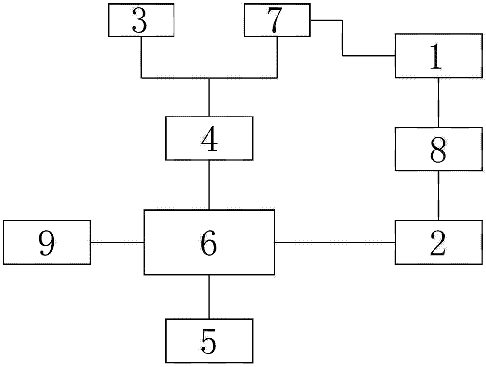
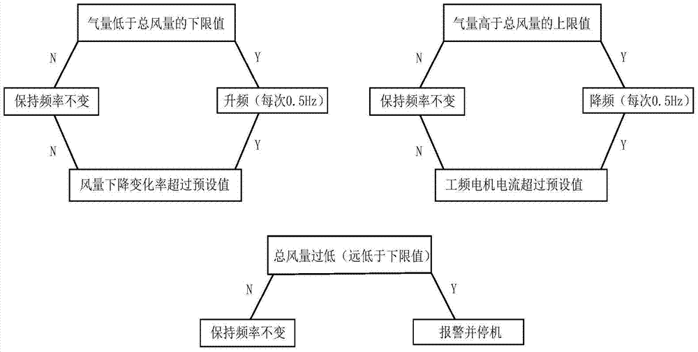
[0022] Attached below Figure 1-2 The blower frequency conversion control device and its control method based on the industrial frequency motor of the present invention are described in detail.

[0023] A blower frequency conversion control device based on a power frequency motor, the blower frequency conversion control device includes a power frequency motor 1, a frequency converter 2, a controller and a communication component; wherein the frequency converter 2 is connected to the power frequency motor 1 through wires, and the controller Controlled connection with the frequency converter through the communication component; the controller includes a storage unit 3, a comparison unit 4, an alarm unit 5, a PLC control unit 6 and a detection unit 7; the storage unit and the detection unit are respectively connected to the comparison unit, the comparison unit and the alarm unit Connected to the PLC control unit respectively; a reactor 8 is also set between the frequency converte...


PUM


Abstract

The invention relates to an air blower variable-frequency control device based on a power frequency motor and a control method for the air blower variable-frequency control device. The air blower variable-frequency control device comprises the power frequency motor, a frequency converter, a controller and a communication assembly, wherein the frequency converter and the power frequency motor are connected by virtue of an electric wire, and the controller is in control connection with the frequency converter by virtue of the communication assembly; the controller comprises a storage unit, a comparison unit, an alarm unit, a PLC (programmable logic controller) control unit and a detecting unit; an electric reactor is further arranged between the frequency converter and the power frequency motor; the detecting unit is connected to the power frequency motor, and is used for feeding back a detected actually-measured frequency value and an actually-measured current value of the power frequency motor, and an outlet total air flow value of the air blower to the comparison unit. The air blower variable-frequency control device has the advantages of being simple in structure, reasonable in design, high in degree of automation, and capable of effectively reducing a calorific value of a frequency converter motor to achieve the purpose of automatically regulating to realize energy saving; and by reasonably controlling and regulating the frequency of the frequency converter, and the occurrence of a surging phenomenon of the air blower due to energy waste or too low frequency caused by too high frequency is avoided.

Description

technical field [0001] The invention relates to the technical field of automatic control, in particular to a frequency conversion control device and a control method for a blower based on a power frequency motor. Background technique [0002] Traditional blowers use forced blowing, and the motor of the blower is always in a state of high-speed operation at the same frequency. The opening of the damper on the equipment is adjusted by means of a linkage mechanism, that is, the air volume is adjusted through the inlet valve; A way to adjust the air volume, so that the motor of the blower runs at the rated rotation speed, resulting in energy waste and economic loss. Gradually, people have adopted frequency conversion to control the motor speed of the blower. However, directly increasing the frequency converter is likely to cause adverse effects such as increased heat generation of the motor and harmonic interference. Therefore, it is of great significance to study a blower cont...

Claims


Application Information

Patent Timeline
Patent Type & Authority Patents(China)
IPC IPC(8): F04D27/02F04D27/00
CPCF04D27/001F04D27/0261
Inventor 李寅李烨郭俊温张建强李慧丽郭毅田振波刘伟岩马文瑾应启峰
Owner XIAOHONGMEN SEWAGE TREATMENT PLANT BEIJING DRAINAGE GRP
Learn More