

Compact centrifugal fan
A centrifugal fan, compact technology, applied in electromechanical devices, mechanical equipment, control mechanical energy, etc., can solve the problems of insufficient diffusion, difficult design of volute parameters, and large wind resistance of the air path, and achieve a state of improving gas flow. , Improve the effect of effective circulation capacity and smooth air flow
- Summary
- Abstract
- Description
- Claims
- Application Information
AI Technical Summary
Problems solved by technology
Method used
Image

Examples
Embodiment 1
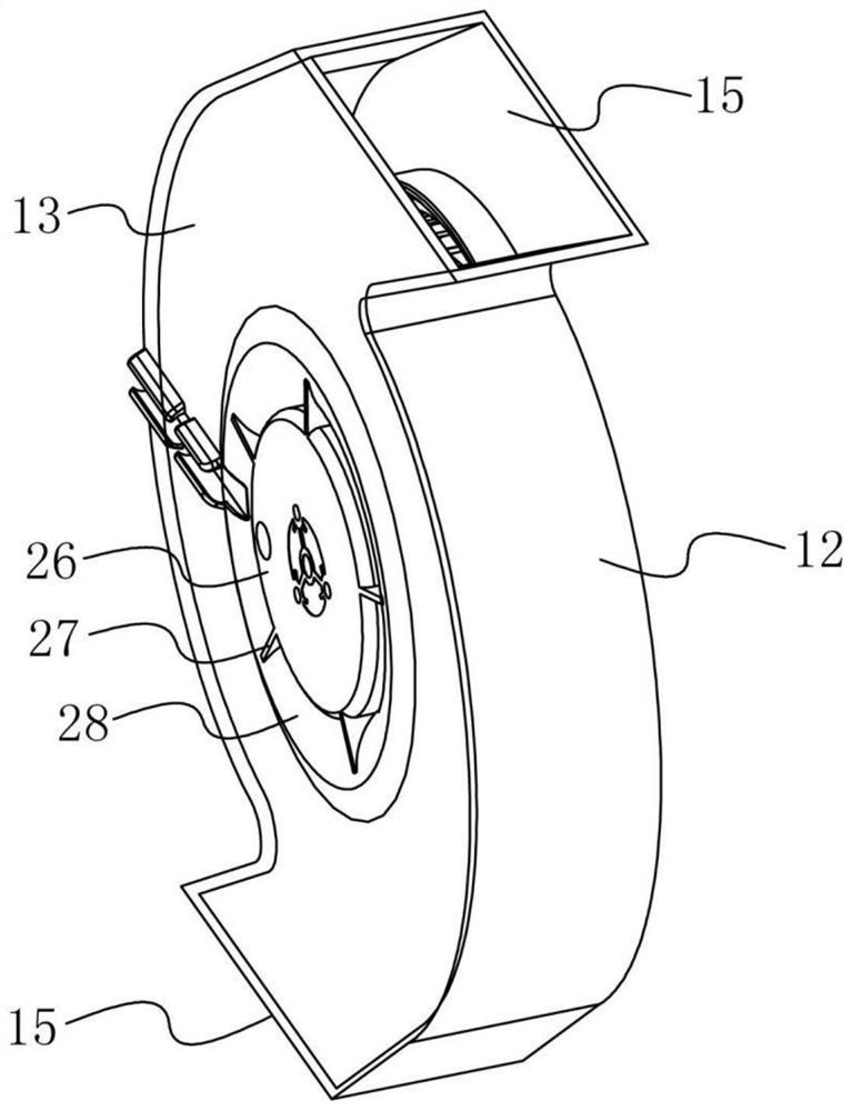
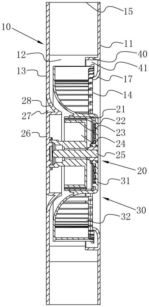
[0034] refer to Figure 1-4 , a compact centrifugal fan, including a volute 10, a driving device 20 and an impeller 30, the driving device 20 is respectively connected with the volute 10 and the impeller 30, and the impeller 30 is rotatably installed in the volute 10.
[0035] The volute 10 includes a front end cover 11, a rear end cover 13, a side plate 12 and a volute tongue 16, the two ends of the side plate 12 are respectively fixedly connected with the front end cover 11 and the rear end cover 13, the air inlet 14 is arranged on the front end cover 11, and the impeller 30 is located between the front end cover 11 and the rear end cover 13 . The anti-vortex ring 40 is fixedly connected with the front end cover 11 . The front end cover 11 is fixedly connected with a deflector 17 located between the anti-vortex ring 40 and the air inlet 14 , and the deflector 17 is bent toward the impeller 30 . The volute tongue 16 is fixedly connected with the side plate 12 and the side w...
Embodiment 2
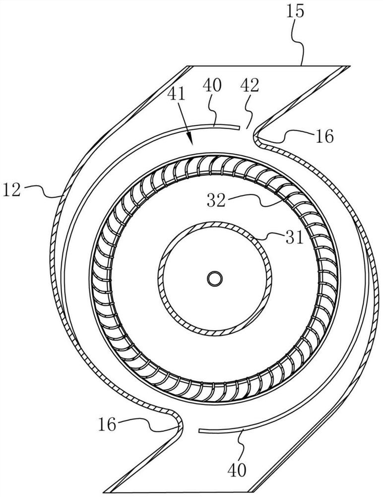
[0068] refer to Figure 6 , a compact centrifugal fan, which is different from the embodiment in that: the anti-vortex ring 40 is in the shape of an annular ring surrounding the impeller 30 as a whole.
[0069] This embodiment has the following advantages:
[0070] The anti-vortex ring 40 is arranged as a ring around the outside of the impeller 30 as a whole, so that the anti-vortex ring 40 can better interfere with the formation of the axial secondary flow, and can effectively weaken the intensity of the axial secondary flow, thereby The state of gas flow inside the volute 10 can be improved, and the effective flow capacity inside the volute 10 is improved.
PUM
| Property | Measurement | Unit |
|---|---|---|
| Thickness | aaaaa | aaaaa |
Abstract
Description
Claims
Application Information