

Spherical spraying nozzle desuperheater
A spherical nozzle and desuperheater technology, applied in the direction of superheating temperature control, steam superheating, steam generation, etc., can solve the problems of poor atomization effect, high energy consumption, low flow rate, etc., and achieve good atomization effect and contact Full, low-noise effect
Inactive Publication Date: 2016-04-06
付开领
View PDF7 Cites 0 Cited by
- Summary
- Abstract
- Description
- Claims
- Application Information
AI Technical Summary
Problems solved by technology
The existing desuperheater often has poor atomization effect, low flow rate and high energy consumption
Method used
View moreImage
Smart ImageViewing Examples

Examples
Embodiment 1
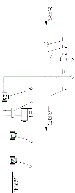
[0011] Example 1. The steam enters the mixing pipe 5 and meets the desuperheating water sprayed from the spherical nozzle 1 located in the middle of the mixing pipe 5. The high temperature carried by the steam is absorbed by the desuperheating water, and its temperature is reduced. The desuperheating water also vaporizes into steam. Due to the spherical design of the nozzle 1 and the uniform distribution of several through holes, the spray range of the desuperheating water is larger, and the distribution of the desuperheating water after spraying is more uniform, so the contact between the desuperheating water and the steam is more sufficient, and the desuperheating effect is more obvious. Temperature accuracy is also higher.
Login to View More PUM
 Abstract
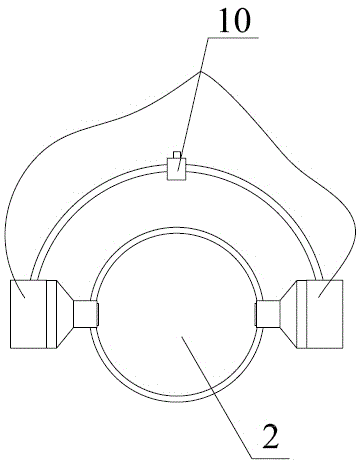
The invention discloses a spherical spraying nozzle desuperheater which is wider in jetting range, better in atomization effect of attemperation water, wider in application range, higher in adjustment accuracy and lower in noise. According to the technical scheme, the spherical spraying nozzle desuperheater is characterized in that a spherical spraying nozzle is fixed in a mixed pipeline through a fixing device; the fixing device is adjustable; through holes are uniformly distributed in the spherical spraying nozzle; one end of a short pipeline is connected with a long pipeline through a connector, and the other end of the short pipeline is connected with the spherical spraying nozzle; and the height of the spherical spraying nozzle is adjustable.
Description
technical field [0001] The invention relates to the field of desuperheating, in particular to a spherical nozzle desuperheater. Background technique [0002] The desuperheater is an important device used to adjust the steam temperature of the steam boiler. In actual life, the temperature of the steam at the outlet of the boiler is often high. At this time, a desuperheater is required to reduce the temperature of the steam to an appropriate range to avoid damage to downstream equipment. Sometimes, because the steam temperature is too high, it may also cause major accidents such as explosions. [0003] The desuperheating effect of the desuperheater is closely related to the amount of sprayed water and the atomization effect of desuperheating water. The existing desuperheaters often have poor atomization effect, low flow rate and high energy consumption. Contents of the invention [0004] In order to overcome the disadvantages of the above-mentioned prior art, the present ...
Claims
Login to View More Application Information
Patent Timeline
 IPC IPC(8): F22G5/12
Inventor付开领黄梅章国方陈建
Owner付开领