Plate heat exchanger

A technology of plate heat exchanger and heat exchange plate, which is applied in the fields of refrigeration, industrial refrigeration, air conditioning, and heating, and can solve the problems of manufacturing large-diameter holes and so on.

Active Publication Date: 2016-04-06
DANFOSS MICRO CHANNEL HEAT EXCHANGER JIAXING
View PDF7 Cites 7 Cited by
  • Summary
  • Abstract
  • Description
  • Claims
  • Application Information

AI Technical Summary

Problems solved by technology

This makes it difficult to make large diamet...

Method used


Image

  • Plate heat exchanger
  • Plate heat exchanger
  • Plate heat exchanger

Examples


Embodiment Construction

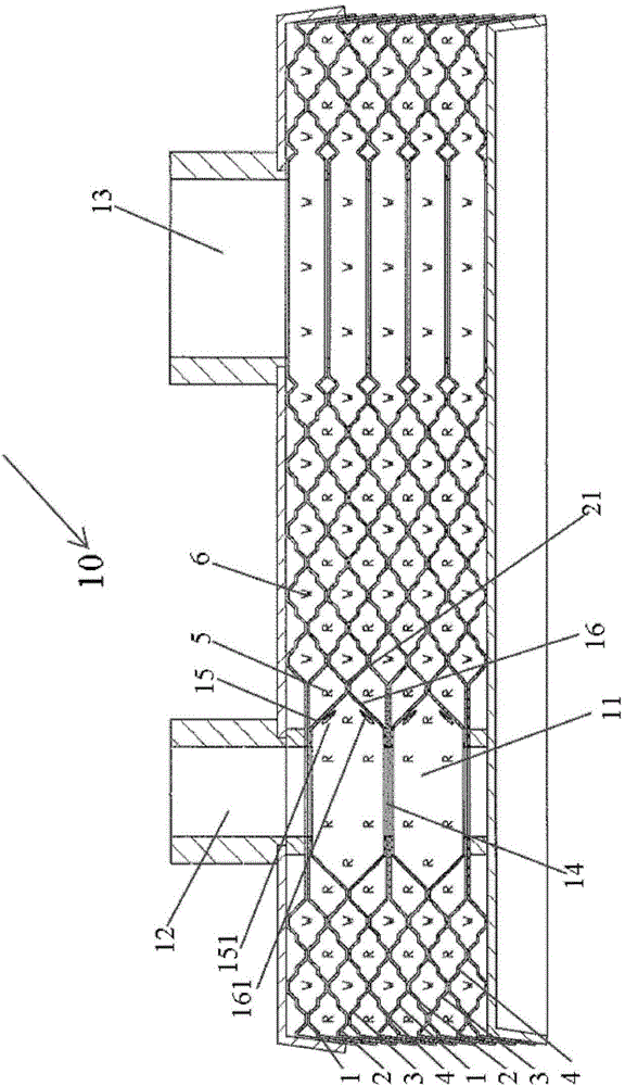
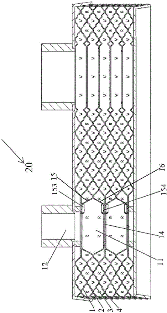
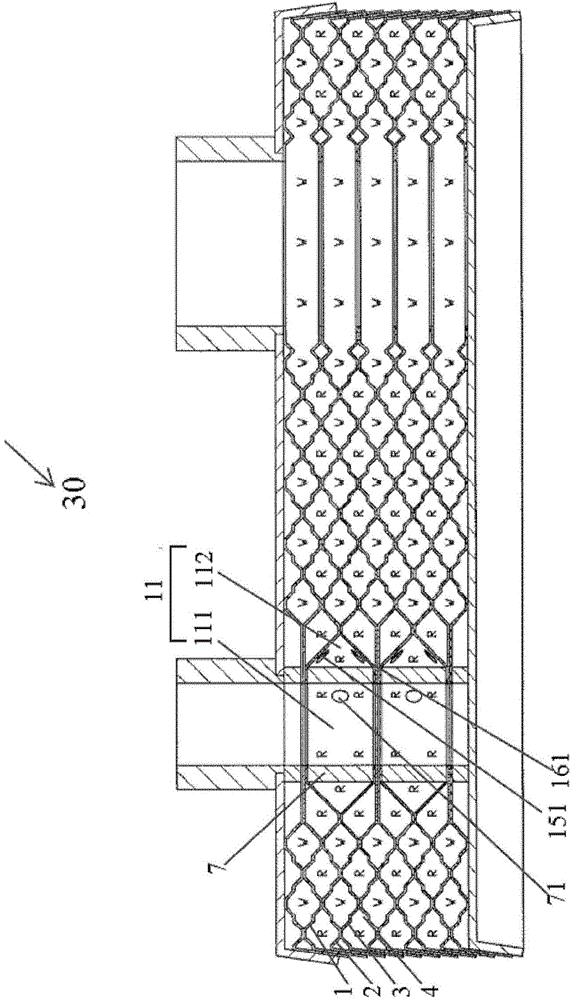
[0033] Through the following examples, combined with the attached Figure 1-6 , the technical solution of the present invention will be further specifically described. In the specification, the same or similar reference numerals designate the same or similar components. The following description of the embodiments of the present invention with reference to the accompanying drawings is intended to explain the general inventive concept of the present invention, but should not be construed as a limitation of the present invention.

[0034] The main idea of ​​the invention is to combine two adjacent fluid channels for the same fluid into one open compartment and to make two holes in the inner wall of said compartment.

[0035] Fluid from the inlet pipes enters the compartment, the flow is split, and passes through the holes of the compartment into each of the respective fluid channels between the heat exchange plates.

[0036] Specifically, such as Figure 1-6 As shown, in some...


PUM


Abstract

The invention discloses a plate heat exchanger comprising a plate assembly. The plate assembly is provided with inlet/outlet passages for two kinds of work medium fluid and comprises first heat exchange plates, second heat exchange plates, third heat exchange plates and fourth heat exchange plates with the peripheries in the same shape. The heat exchange plates are sequentially arranged according to the cycle of the first heat exchange plates, the second heat exchange plates, the third heat exchange plates and the fourth heat exchange plates. First fluid passages where first fluid passes are arranged between the first heat exchange plates and the second heat exchange plates as well as between the third heat exchange plates and the fourth heat exchange plates. Second fluid passages where second fluid passes are arranged between the second heat exchange plates and the third heat exchange plates as well as between the fourth heat exchange plates and the adjacent first heat exchange plates. The plate assembly further comprises at least one separation space communicated with the two adjacent first fluid passages. The separation spaces are closed relative to the second fluid passages. For each separation space, the first and the second heat exchange plates are arranged at the first side, and the third and the fourth heat exchange plates are arranged at the second side opposite to the first side.

Description

technical field [0001] The invention relates to the fields of refrigeration, air conditioning, industrial refrigeration, heating and the like, and particularly relates to a plate heat exchanger. Background technique [0002] For two-phase flow inside a plate heat exchanger, the fluid distribution between the different fluid channels between the heat exchange plates is always a challenge to achieve high efficiency and reliability. [0003] Existing fluid distribution devices can be O-rings, plug-in distributors, guide tubes, etc. But as the heat flow and crimp depth decrease, the holes in the dispensing device are getting smaller and smaller, which results in high and tight tolerances for the holes. What's more, it is becoming increasingly difficult to manufacture very small holes with such tight tolerances. Moreover, this also leads to a rapid increase in the cost of the dispensing device. [0004] As the diameter of the holes continues to decrease, it becomes more and mo...

Claims


Application Information

Patent Timeline
IPC IPC(8): F28D9/00
CPCF28D9/04F28F3/08
Inventor 魏文建张志锋
Owner DANFOSS MICRO CHANNEL HEAT EXCHANGER JIAXING
Why Eureka
Try Eureka