A mos tube fixing structure and fixing method

A technology of MOS tube and fixed structure, which is applied in the direction of electric solid-state devices, semiconductor/solid-state device components, printed circuits connected with non-printed electrical components, etc., can solve the problems of low assembly efficiency and breakdown, and achieve improvement Work efficiency, flat and tight fit, and the effect of reducing production costs

Inactive Publication Date: 2018-08-31
上海兆能电力电子技术有限公司
View PDF5 Cites 0 Cited by
  • Summary
  • Abstract
  • Description
  • Claims
  • Application Information

AI Technical Summary

Problems solved by technology

At present, the widely used fixing structure is fixed by screw fixing structure, but the assembly efficiency of screw fixing structure is low, and the MOS tube after fixing has rotational stress, and there is a risk of being broken down

Method used


Image

  • A mos tube fixing structure and fixing method
  • A mos tube fixing structure and fixing method
  • A mos tube fixing structure and fixing method

Examples


Embodiment Construction

[0028] The technical solutions of the present invention will be further described below in conjunction with the accompanying drawings and through specific implementation methods.

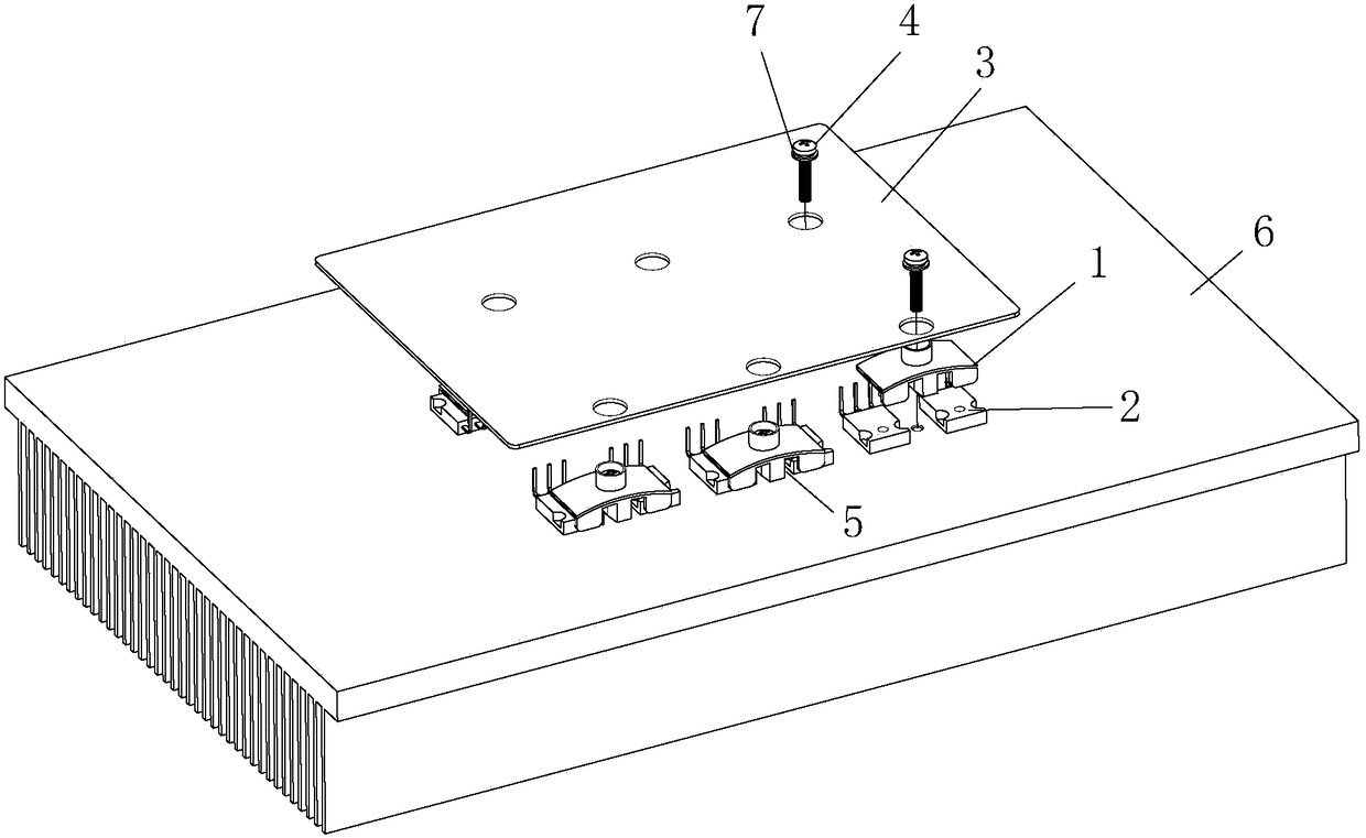
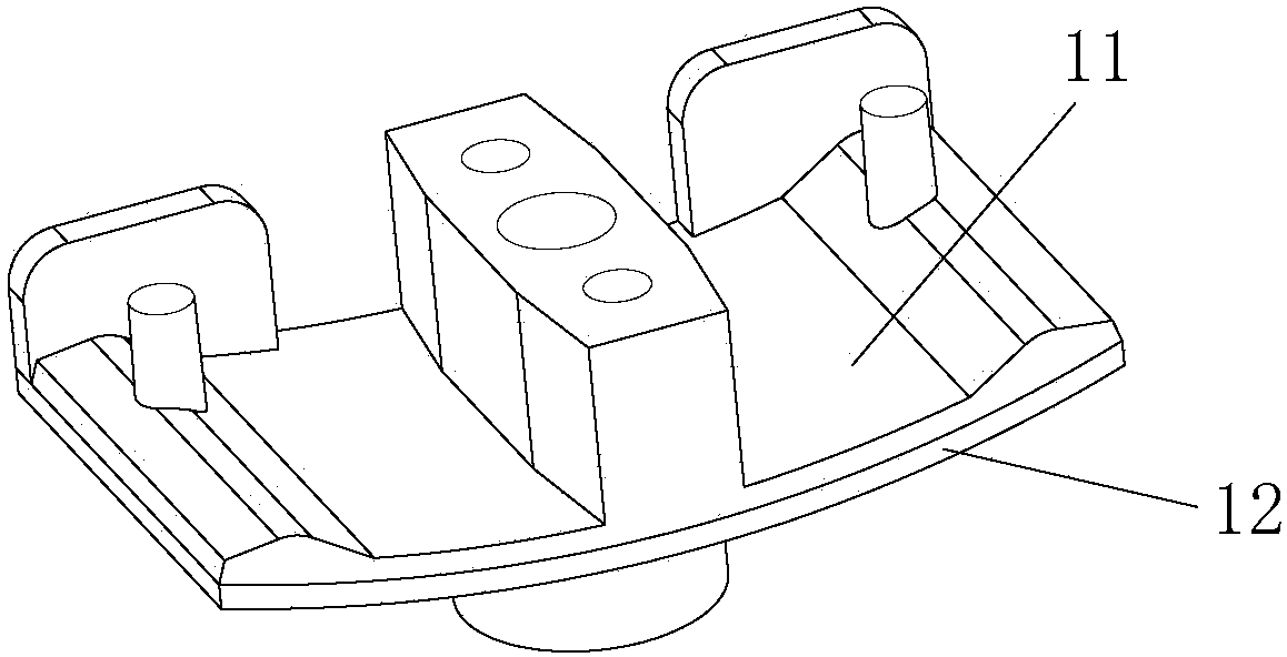
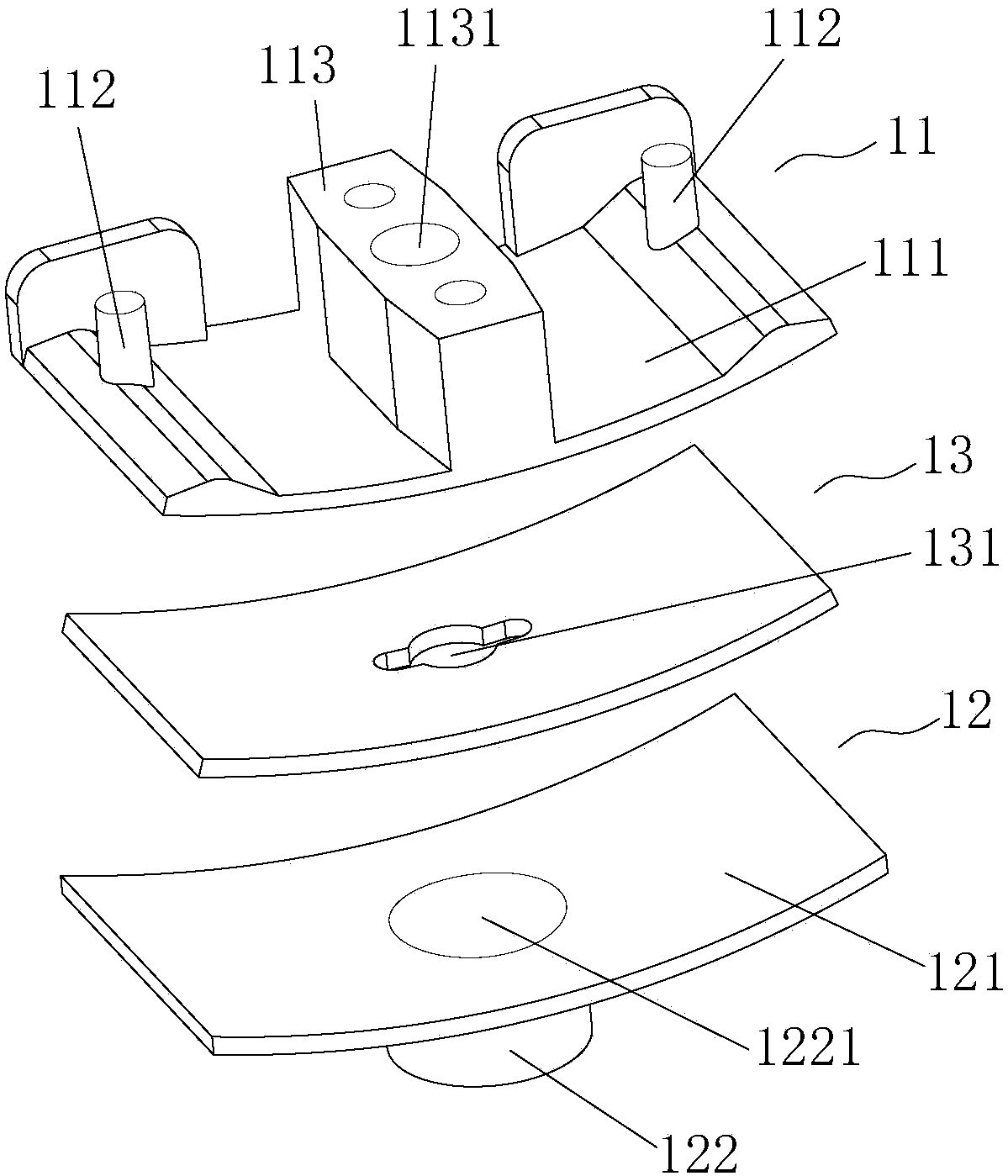
[0029] This embodiment provides a MOS tube fixing structure, so that the MOS tube 2 and the heat sink always have good contact and heat dissipation. In this example, if figure 1 As shown, the pins of the MOS tube 2 are welded on the PCB board 3, and the side of the MOS tube 2 away from the PCB board 3 is provided with a radiator 6; the fixed structure includes an accommodation space formed between the MOS tube 2 and the PCB board 3 5, and one end of it protrudes from the PCB board 3, and the other end is fastened and connected with the MOS tube 2; it also includes a screw 4, the fixing part 1 and the radiator 6 are connected by the screw 4, and the upper end of the screw 4 is clamped on the fixing part 1 protruding from one end of the PCB board 3, and its lower end penetrates from the end of the fi...


PUM


Abstract

The invention discloses a fixing structure and a fixing method for an MOS transistor. The MOS transistor pin is welded on a PCB; the fixing structure comprises a fixing part that is positioned in an accommodating space formed by the MOS transistor and the PCB; one end of the fixing part extends out of the PCB while the other end of the fixing part is connected with the MOS transistor in a buckling manner; the fixing structure also comprises a screw; the fixing part is connected with a radiator through the screw; the upper end of the screw is clamped at one end, extending out of the PCB, of the fixing part while the lower end of the screw penetrates from one end, extending out of the PCB, of the fixing part, and the screw extends out of one end, buckled with the MOS transistor, of the fixing part to be rotated into the radiator; the fixing part adopts an arc-shaped structure, and can be deformed in a central axial direction of the screw; and when the screw penetrates through the fixing part to be rotated into the radiator, the fixing part is deformed from the arc-shaped structure into a flat-plate structure for pushing against the MOS transistor on the radiator. The fixing structure can fix two MOS transistors at the same time, so that the working efficiency is improved; and when the screw penetrates through the fixing part to be rotated into the radiator, the fixing part is deformed for applying action force on the MOS transistor to enable the MOS transistor to be smoothly and tightly laminated with the radiator so as to improve the radiating effect.

Description

technical field [0001] The invention relates to a fixing technology of a MOS tube, in particular to a fixing structure and a fixing method of a MOS tube. Background technique [0002] With the rapid development of industrialization, the application of MOS tubes is becoming more and more extensive, and the requirements for its fixed structure are also getting higher and higher. The currently widely used fixing structure is fixed by a screw fixing structure, but the assembly efficiency of the screw fixing structure is low, and the MOS tube after fixing has rotational stress, and there is a risk of being broken down. Contents of the invention [0003] The purpose of the present invention is to provide a MOS tube fixing structure with a simple structure, reduce production cost, make the MOS tube and the heat sink fit closely, and improve the heat dissipation effect. [0004] The invention also provides a method for fixing the MOS tube, which simplifies the way of fixing the M...

Claims


Application Information

Patent Timeline
Patent Type & Authority Patents(China)
IPC IPC(8): H01L23/40H05K1/18
Inventor 曾学飞何俊峰郑洪涛
Owner 上海兆能电力电子技术有限公司
Why Eureka
Try Eureka