MOS transistor fixing structure and mounting method thereof

A MOS tube and fixed structure technology, applied in the field of MOS tubes, can solve the problems of high process requirements, high cost of use, complicated procedures, etc., and achieve the effect of simple fixing method, low cost and simple mold

Inactive Publication Date: 2015-03-25
ATECH AUTOMOTIVE WUHU
View PDF7 Cites 2 Cited by
  • Summary
  • Abstract
  • Description
  • Claims
  • Application Information

AI Technical Summary

Problems solved by technology

[0003] In the process of realizing the present invention, the inventors found that there are at least the following problems in the prior art: in general, screw fixing requires a screw for each MOS tube, the process is complicated, and there is a risk of short circuit; The MOS tube is pasted on the aluminum substrate, and then pasted on the heat sink through the aluminum substrate. This structure has high cost and many processes, and the process requirements are also very high.

Method used


Image

  • MOS transistor fixing structure and mounting method thereof
  • MOS transistor fixing structure and mounting method thereof
  • MOS transistor fixing structure and mounting method thereof

Examples


Embodiment Construction

[0021] In order to make the object, technical solution and advantages of the present invention clearer, the implementation manner of the present invention will be further described in detail below in conjunction with the accompanying drawings.

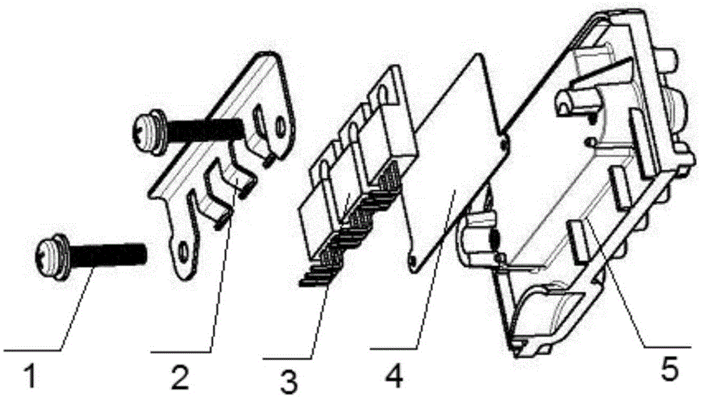
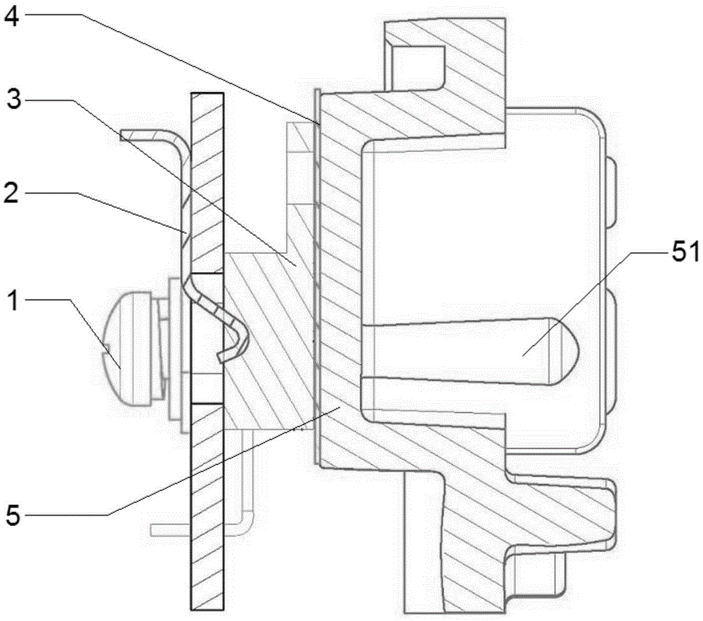
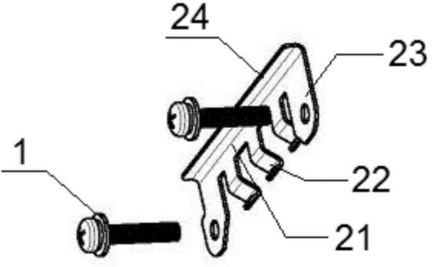
[0022] see figure 1 with figure 2 , a MOS tube fixing structure, including MOS tube 3 and heat sink 5, also includes shrapnel 2, such as image 3 As shown, the shrapnel 2 includes a body portion 21, and the body portion 21 is provided with an outwardly protruding, elastically deformable clamping portion 22. The shrapnel 2 and the heat sink 5 are connected by screws 1, and the MOS tube 3 is clamped in the clamping portion. Between the tight part 22 and the heat sink 5;

[0023] Both sides of the body portion 21 are also provided with an outwardly extending extension portion 23, and the extension portion 23 is provided with a through hole for the screw 1 to pass through. The screw 1 is screwed to the screw seat 51 on the heat sink 5. ...


PUM


Abstract

The invention discloses an MOS transistor fixing structure and a mounting method thereof. The fixing structure comprises an MOS transistor (3), a radiating fin (5) and an elastic piece (2) which comprises a body part (21). The body part (21) is provided with an outward protrusion and a clamping part (22) which can carry out elastic deforming. The elastic piece (2) and the radiating fin (5) are connected through screws (1), and the MOS transistor (3) is clamped between the clamping part (22) and the radiating fin (5). Extending parts (23) which extend outwards are arranged on the two sides of the body part (21). Through holes which can be used for the screws (1) to penetrate through are formed in the extending parts (23). The screws (1) are in thread connection with a screw base (51) on the radiating fin (5). According to the positions of the extending parts (23), the screws (1) are not in contact with the MOS transistor (3), a fixing mode is simple, high efficiency is achieved, cost is low, and the MOS transistor fixing structure is especially practical for a structure where the MOS transistor (3) is used in a large area.

Description

technical field [0001] The invention belongs to the technical field of MOS tubes, in particular to a MOS tube fixing structure and an installation method thereof. Background technique [0002] With the rapid development of industry, the fields that need to be controlled by MOS are becoming more and more extensive, and the fixing methods of MOS tubes (metal-oxide-semiconductor field effect transistors) are also various. Ordinary MOS tubes use screws, patches, etc., and then contact the heat sink, [0003] In the process of realizing the present invention, the inventors found that there are at least the following problems in the prior art: in general, screw fixing requires a screw for each MOS tube, the process is complicated, and there is a risk of short circuit; The MOS tube is pasted on the aluminum substrate, and then pasted on the heat sink through the aluminum substrate. This structure has a high cost of use, more processes, and very high process requirements. Content...

Claims


Application Information

Patent Timeline
Patent Type & Authority Applications(China)
IPC IPC(8): H01L23/40H01L21/48
Inventor 陈泽坚
Owner ATECH AUTOMOTIVE WUHU
Why Eureka
Try Eureka