Energy storage system for charging electric vehicle

A technology for electric vehicles and energy storage systems, applied in electric vehicle charging technology, electric vehicles, vehicle energy storage, etc., can solve problems such as affecting the enthusiasm of electric vehicle users, affecting the promotion of electric vehicles, and interruption of power input.

Inactive Publication Date: 2016-04-06
XIAN TGOOD INTELLIGENT CHARGING TECH CO LTD
View PDF4 Cites 5 Cited by
  • Summary
  • Abstract
  • Description
  • Claims
  • Application Information

AI Technical Summary

Problems solved by technology

When the power supply grid is suddenly disconnected, the power input of the entire electric vehicle charging system will be interrupted, which will cause at least two effects
1. The electric car that is being charged cannot continue to be charged, and at the same time, due to a power outage, the charging power of the electric car cannot be uploaded to the cloud background
2. Electric vehicles waiting to be charged cannot be charged normally
The power outage of the charging station and the sudden cut off of the output of electric energy will greatly affect the enthusiasm of electric vehicle users and affect the promotion of electric vehicles in the future.

Method used


Image

  • Energy storage system for charging electric vehicle
  • Energy storage system for charging electric vehicle
  • Energy storage system for charging electric vehicle

Examples


Embodiment 1

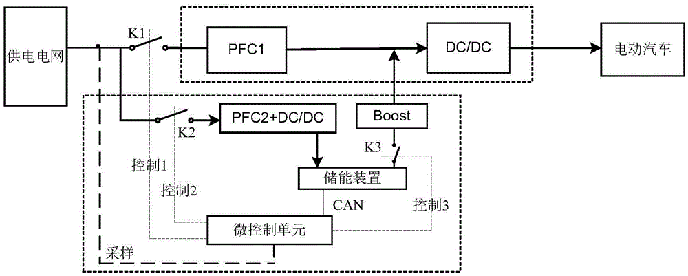
[0024] see figure 2 A first switch K1 is arranged between the power supply grid and the charger, the charger includes a first power factor corrector PFC1 connected to the first switch K1, and the first power factor corrector PFC1 is connected to the electric vehicle through a first DC / DC converter, The power supply grid is also connected to a second power factor corrector PFC2, a second switch K2 is arranged between the power supply grid and the second power factor corrector PFC2, and the second power factor corrector PFC2 is connected to the energy storage device through a second DC / DC converter , the energy storage device is connected to the input end of the first DC / DC converter after passing through the boost circuit, a third switch K3 is arranged between the energy storage device and the boost unit, and the energy storage device is also connected to a micro control unit, the micro control unit The information of the power supply grid can be collected, and the first switc...

Embodiment 2

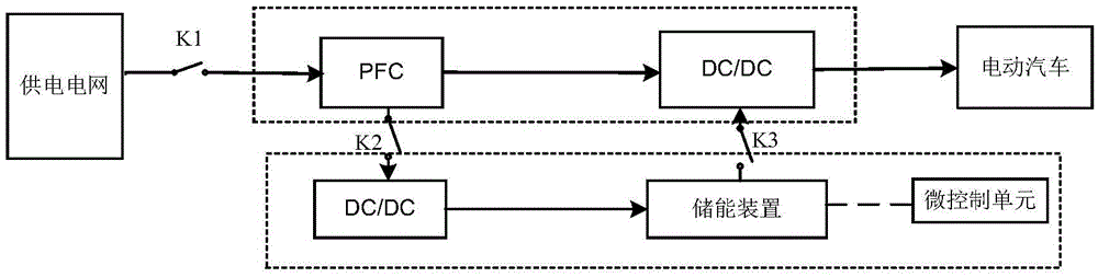
[0029] see image 3 A first switch K1 is arranged between the power supply grid and the charger, the charger includes a power factor corrector PFC connected to the first switch K1, the power factor corrector PFC is connected to the electric vehicle through the first DC / DC converter, and the power factor corrector The output end of the PFC is connected to the energy storage module through the second switch K2 and the second DC / DC converter, the energy storage module is connected to the input end of the third DC / DC converter through the third switch K3, and the energy storage module is also connected to a micro-controller unit, the micro control unit can collect the information of the power supply grid, and control the first switch K1, the second switch K2 and the third switch K3.

[0030] The power supply grid normally outputs electric energy (three-phase 380V), the first switch K1 is closed, the electric energy is corrected by the power factor corrector PFC and converted from ...

Embodiment 3

[0035] see Figure 4 A first switch K1 is arranged between the power supply grid and the charger, the charger includes a power factor corrector PFC connected to the first switch K1, the power factor corrector PFC is connected to the electric vehicle through the first DC / DC converter, and the power factor corrector The output end of the PFC is connected to the energy storage module through the third switch K3 and the second DC / DC converter, the energy storage module is connected to the input end of the power factor corrector PFC through the second switch K2 and the DC / AC converter, and the energy storage module is also A micro control unit is connected, and the micro control unit can collect the information of the power supply grid, and control the first switch K1, the second switch K2 and the third switch K3.

[0036] The power supply grid normally outputs electric energy (three-phase 380V), the first switch K1 is closed, the electric energy is corrected by the factor correcto...


PUM


Abstract

The invention discloses an energy storage system for charging an electric vehicle. The energy storage system comprises a power supply network, wherein the power supply network is connected with a charger with an energy storage device; the charger with the energy storage device is connected with the electric vehicle and comprises a charger body which is connected with the power supply network and the electric vehicle; the charger is also connected with the energy storage device; and the energy storage device is controlled through a micro control unit. The energy storage device is added to the front end of an existing direct-current charging system; when the power network is powered off, the electric energy of the energy storage device is input into the direct-current charging system, so that uninterruptible power supply of an electric vehicle charging system is achieved; when the power network is normal, the electric energy is directly input into the direct-current charging system from a bypass; and meanwhile, when the energy storage device is short of electricity, the control unit transmits a signal and a switch at an input end of the energy storage device is turned off, so that the target of charging the energy storage device is achieved.

Description

【Technical field】 [0001] The invention belongs to the field of electric vehicle charging, and in particular relates to an electric vehicle charging energy storage system. 【Background technique】 [0002] With the progress of society and the enhancement of environmental protection awareness, electric vehicles are gradually favored because they are powered by vehicle-mounted power supplies and can solve the problems of exhaust emissions from fuel vehicles, pollution of the environment, and high energy consumption. And the charging problem of electric vehicle is the problem that people pay close attention to very much, and it is related to popularization and promotion of electric vehicle. [0003] The input of the electric vehicle charging system is the low-voltage output 380V of the substation. When the power supply grid is suddenly disconnected, the power input of the entire electric vehicle charging system will be interrupted, which will cause at least two effects. 1. The e...

Claims


Application Information

Patent Timeline
Patent Type & Authority Applications(China)
IPC IPC(8): H02J7/02H02J7/00H02J9/06
CPCB60L53/24H02J7/02H02J7/022H02J7/342H02J9/06Y02T10/70Y02T10/7072Y02T90/14
Inventor 袁庆民
Owner XIAN TGOOD INTELLIGENT CHARGING TECH CO LTD
Why Eureka
Try Eureka