Peak current detection compensation circuit and peak current detection compensation method

A technology of peak current and compensation circuit, which is applied in the field of switching power supply, can solve the problems that the current exceeds the preset threshold and cannot achieve constant peak current control, etc.

Inactive Publication Date: 2016-04-06
JOULWATT TECH INC LTD
View PDF3 Cites 3 Cited by
  • Summary
  • Abstract
  • Description
  • Claims
  • Application Information

AI Technical Summary

Problems solved by technology

[0005] The purpose of the present invention is to provide a peak current detection and compensation circuit and a peak current detection and compensation method to solve the problem that the current of the existing peak current control circuit exceeds the preset threshold and cannot achieve constant peak current control

Method used


Image

  • Peak current detection compensation circuit and peak current detection compensation method
  • Peak current detection compensation circuit and peak current detection compensation method
  • Peak current detection compensation circuit and peak current detection compensation method

Examples


Embodiment Construction

[0024] The technical solutions of the present invention will be clearly and completely described below through specific embodiments in conjunction with the accompanying drawings.

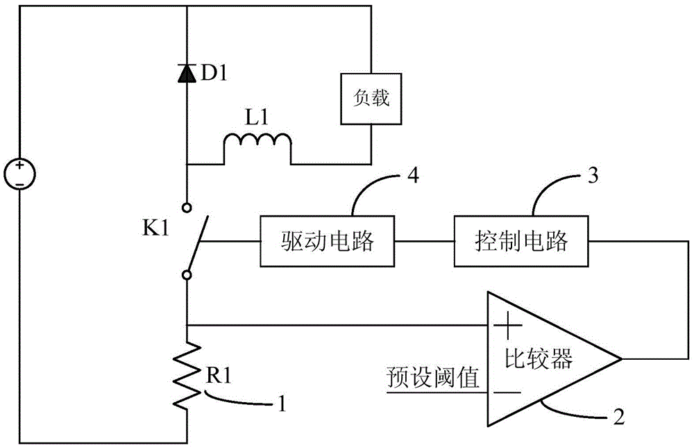
[0025] The invention discloses a peak current detection and compensation circuit, please refer to Figure 4 , the peak current detection and compensation circuit of the present invention includes a second switching tube K2, a second inductor L2, a load 11, a second freewheeling diode D2, a current sampling circuit 5, a peak sampling and holding circuit 6, a reference signal adjustment circuit 7, a comparator 8. A control circuit 9 and a drive circuit 10 .

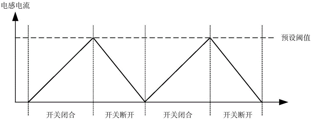
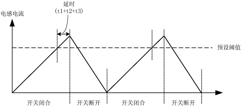
[0026] In this embodiment, the peak current detection and compensation circuit of the present invention is used for peak detection of the current of the second inductor L2, and dynamically adjusts the reference signal of the comparator to ensure that the peak value of the current of the second inductor L2 is equal to the preset threshold. A seco...


PUM


Abstract

The invention discloses a peak current detection compensation circuit and a peak current detection compensation method. The peak current detection compensation circuit comprises a switching tube, a current sampling circuit and a comparator, wherein the current sampling circuit is electrically connected with the switching tube and used for sampling current passing through the switching tube or an inductor; the sampling output end of the current sampling circuit outputs a sampling signal; the first input end of the comparator is connected with the sampling end of the current sampling circuit while the second input end of the comparator is connected with a dynamic reference signal; the dynamic reference signal is accordingly adjusted according to a comparison result between the peak value of the sampling value and a preset threshold value; when the sampling signal is greater than the dynamic reference signal, the output end of the comparator outputs a switching tube disconnecting signal; the peak current detection compensation method comprises the steps of obtaining the sampling signal; comparing the peak value of the sampling value with the preset threshold value, and outputting the dynamic reference signal; comparing the sampling signal with the dynamic reference signal, and when the sampling signal is greater than the dynamic reference signal, outputting the switching tube disconnecting signal.

Description

technical field [0001] The invention relates to the field of switching power supplies, in particular to a peak current detection and compensation circuit and a peak current detection and compensation method. Background technique [0002] In current-mode switching power supplies, peak current control is a commonly used control method. Its basic principle is to detect the inductor current value in real time through the comparator in the peak current control circuit, and then control the peak value of the inductor current to a constant value. [0003] Please refer to figure 1 , the traditional peak current control circuit includes a first switching tube K1, a first inductor L1, a load, a first freewheeling diode D1, a current sampling resistor 1, a comparator 2, a control circuit 3, a driving circuit 4, a current sampling resistor 1 and The first switching tube K1 is connected in series, the comparator 2, the control circuit 3 and the driving circuit 4 are sequentially connect...

Claims


Application Information

Patent Timeline
Patent Type & Authority Applications(China)
IPC IPC(8): H02M1/00
CPCH02M1/00H02M1/0025
Inventor 白浪黄必亮任远程周逊伟
Owner JOULWATT TECH INC LTD
Why Eureka
Try Eureka