
Pressure relief valve and pressure cooker for pressure cooker

A pressure cooker and pressure relief valve technology, applied in the field of pressure cookers, can solve problems such as hidden safety hazards and pressure relief valve failure, and achieve the effect of safe and reliable use

Active Publication Date: 2017-10-20
WUHAN SUPOR COOKWARE
View PDF5 Cites 0 Cited by
  • Summary
  • Abstract
  • Description
  • Claims
  • Application Information

AI Technical Summary

Problems solved by technology

However, after long-term use, the lower end of the valve core will stick to the seal. Even if the pressure in the pot exceeds a certain value, the lower end of the valve core cannot open the through hole.

Method used


Image

  • Pressure relief valve and pressure cooker for pressure cooker
  • Pressure relief valve and pressure cooker for pressure cooker
  • Pressure relief valve and pressure cooker for pressure cooker

Examples


Embodiment Construction

[0026] The present invention will be described in further detail below in conjunction with the accompanying drawings and specific embodiments, but these embodiments should not be construed as limiting the present invention.

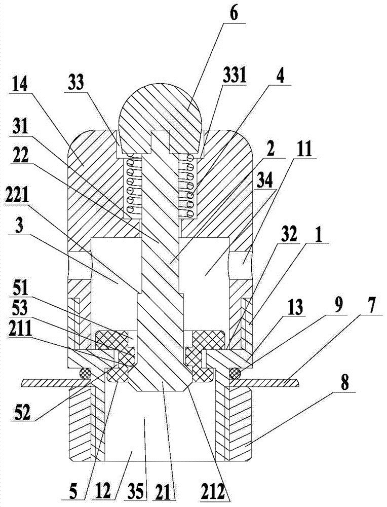
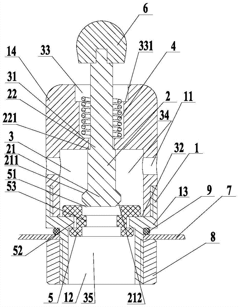
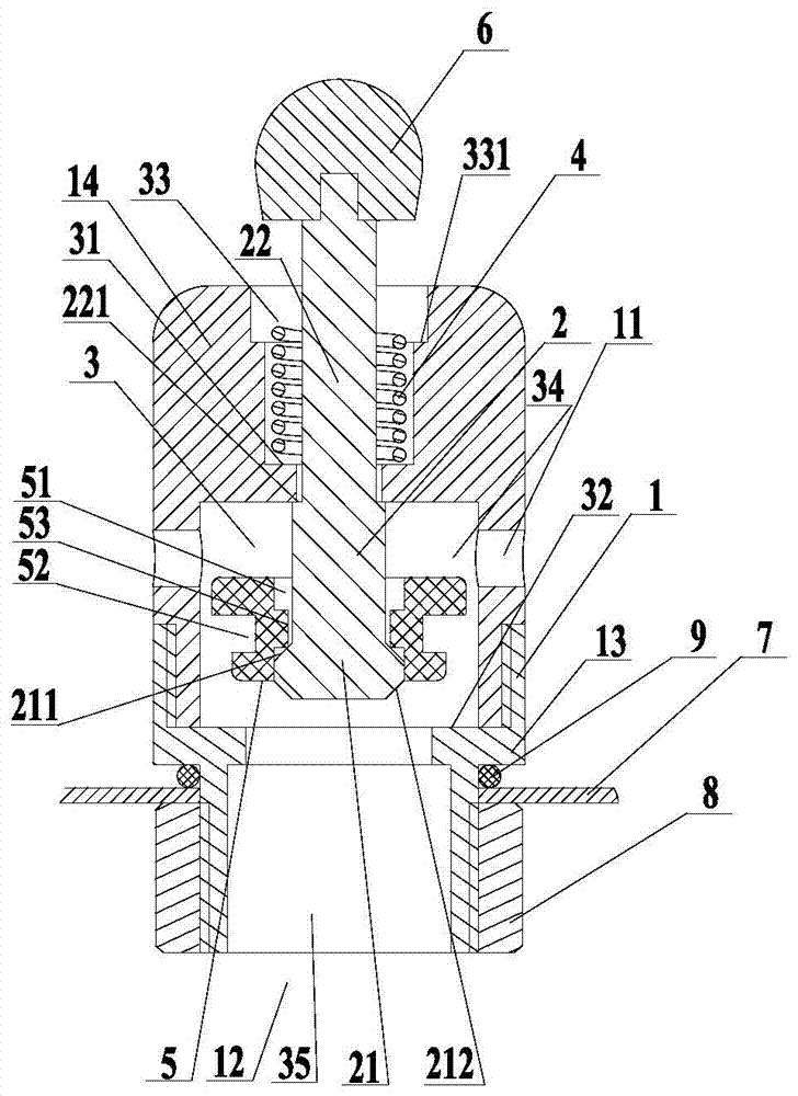
[0027] Please refer to figure 1 with figure 2 , a pressure relief valve for a pressure cooker provided by the present invention, comprising a valve seat 1 and a valve core 2 . Wherein, the valve seat 1 includes a valve sleeve 13 and a valve cover 14 which are screwed together. The valve cover 14 is provided with a plurality of radial exhaust holes 11 , and the valve sleeve 13 is provided with an air inlet 12 . The valve sleeve 13 and the valve cover 14 form a stepped passage 3 running through the two opposite ends thereof, the valve cover 14 is provided with a first step 31 in the stepped passage 3 , and the valve sleeve 13 is provided with a second step 32 in the stepped passage 3 . The first step 31 and the second step 32 divide the step passage 3 in...


PUM


Abstract

The invention discloses a pressure release valve used for a pressure cooker and the pressure cooker. The pressure release valve comprises a valve seat and a valve element. The valve element comprises a sealing part and a valve rod connected with the sealing part. A step passageway penetrating through the two opposite ends of the valve seat is arranged on the valve seat. A first step and a second step are arranged in the step passageway. Exhaust holes communicated with the step passageway are formed in the portion, between the first step and the second step, of the valve seat. The pressure release valve further comprises an elastic reset piece and an elastic sealing body. A valve rod is sleeved with the elastic reset piece. The two opposite ends of the elastic reset piece can elastically abut against the valve rod and the first step respectively. The elastic sealing body is arranged on the second step and arranged on the valve rod in a sleeving mode. A through hole for the valve rod to penetrate through is formed in the elastic sealing body. The sealing part abuts against the bottom face of the elastic sealing body and seals the through hole. The sealing part is pushed by pressure to penetrate through the through hole and move to the space between the first step and the second step. Rapid and stable exhausting can be achieved; meanwhile, the two-stage pressure release function is achieved, and it is ensured that use of the pressure cooker is safer and more reliable.

Description

technical field [0001] The invention relates to the technical field of pressure cookers, in particular to a pressure relief valve for a pressure cooker and a pressure cooker. Background technique [0002] On the lid of the pressure cooker, in addition to the pressure limiting valve, some safety devices are also provided to prevent explosion accidents from occurring after the pressure limiting valve is blocked. These safety devices are usually pressure relief valves. After the pressure limiting valve is blocked, the high pressure in the pressure cooker will make the pressure relief valve in a pressure relief state, and the gas will be discharged from the pressure relief valve. At present, the pressure relief valve used in the pressure cooker is the skylight pressure relief mechanism. When the pressure in the pressure cooker exceeds a certain value, the skylight pressure relief mechanism will quickly release the gas in the pot. During the pressure relief process, the sealing r...

Claims


Application Information

Patent Timeline
Patent Type & Authority Patents(China)
IPC IPC(8): A47J27/09
CPCA47J27/09
Inventor 李志超王璞邱波
Owner WUHAN SUPOR COOKWARE
Learn More