Cutting insert with asymmetric cutting edge

一种切削刀片、切削刃的技术,应用在双面正方形可转位的切削刀片领域,能够解决增加高度等问题

Inactive Publication Date: 2016-04-13
KENNAMETAL INC
View PDF4 Cites 1 Cited by
  • Summary
  • Abstract
  • Description
  • Claims
  • Application Information

AI Technical Summary

Problems solved by technology

[0003] By providing a cutting insert with an asymmetrical cutting edge with respect to the central longitudinal axis of the cutting insert, the problem of increasing the height of the shoulder available for cutting by the cutting insert is solved

Method used


Image

  • Cutting insert with asymmetric cutting edge
  • Cutting insert with asymmetric cutting edge
  • Cutting insert with asymmetric cutting edge

Examples


Embodiment Construction

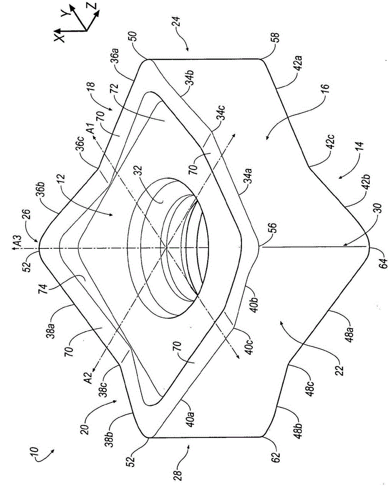
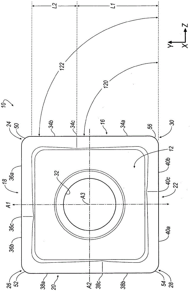
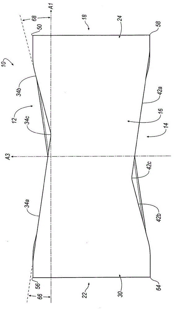
[0014] see now Figure 1-Figure 3 , shows a cutting insert 10 according to an embodiment of the invention. In general, the cutting insert 10 is double-sided, indexable and equidistant. The cutting insert 10 is typically manufactured by forming pressed and cemented carbide powder using methods known in the art. The cutting insert 10 is generally square in shape and has two identical opposing first and second surfaces 12, 14, and four circumferential side surfaces 16 extending entirely between the first and second surfaces 12, 14. , 18, 20, 22. The first surface 12 and the second surface 14 are substantially identical to each other, and the four circumferential side surfaces 16, 18, 20, 22 are substantially identical to each other. The cutting insert 10 also includes four curved corners 24 , 26 , 28 , 30 extending entirely between the first surface 12 and the second surface 14 and adjacent circumferential side surfaces 16 , 18 , 20 , 22 . The first surface 12 and the second ...


PUM


Abstract

A cutting blade having asymmetric cutting edges is provided. The cutting inserts generally square-shaped with two opposing surfaces and four peripheral side surfaces. Cutting edges are formed at the intersection between the first and second surfaces and the peripheral side surfaces. Each cutting edge is divided into a first portion, a second portion and a radius blend. The first portion has a length, L1, and the second portion has a length, L2, that is shorter than the first portion such that the radius blend is not located at a midpoint of the cutting edge, thereby increasing a height of the ninety-degree shoulder that can be cut by the cutting insert.

Description

technical field [0001] The present invention relates generally to cutting inserts and cutting tools, and in particular to equiaxially mounted double-sided square indexable cutting inserts for milling cutters having linear cutting edges and curved chamfers. Background technique [0002] Milling cutters need to be equipped with cutting inserts with a main cutting edge for milling a 90 degree shoulder in the workpiece. The cutting blade protrudes beyond the end face of the rotatable tool holder when clamped and also protrudes laterally in order to be able to create a vertical wall section and complete the cutting bed wall. In most milling cutters, the height of the achievable shoulder is limited by the length of the main cutting edge, especially in cutting inserts that are not square in shape. Contents of the invention [0003] By providing the cutting insert with an asymmetrical cutting edge with respect to the central longitudinal axis of the cutting insert, the problem of...

Claims


Application Information

Patent Timeline
Patent Type & Authority Applications(China)
IPC IPC(8): B23C5/08B23C5/20
CPCB23C5/08B23C2200/0455B23C2210/204B23C5/202B23C5/06B23C2200/205
Inventor B·D·霍弗J·F·科瓦克
Owner KENNAMETAL INC
Why Eureka
Try Eureka