Cutting mechanism with clamping device

A technology of cutting mechanism and clamping device, which is applied in the direction of shearing device, accessory device of shearing machine, metal processing equipment, etc., and can solve problems such as difficult cutting of cutting machine fixture

Inactive Publication Date: 2016-04-13
LUZHOU YUANCHENG ENG MACHINERY CO LTD
View PDF9 Cites 6 Cited by
  • Summary
  • Abstract
  • Description
  • Claims
  • Application Information

AI Technical Summary

Problems solved by technology

[0004] The purpose of the present invention is to provide a cutting mechanism with its own clamping device, which solves the problem that it is difficult to clamp and cut both flat and curved surfaces in the cutting machine clamps in the prior art, and realizes that a set of devices can be used to cut flat workpieces. or curved workpieces can be cut
Aiming at the problem that it is difficult for the existing cutting machine clamps to clamp both flat and curved surfaces for cutting, the present invention proposes a cutting mechanism with its own clamping device. The holding plate, and the rotating shaft that drives the holding plate to rotate, realize the convenient and fast replacement of the holding surface, so as to achieve the purpose of cutting both flat workpieces and curved surface workpieces with one set of devices

Method used


Image

  • Cutting mechanism with clamping device
  • Cutting mechanism with clamping device
  • Cutting mechanism with clamping device

Examples


Embodiment 1

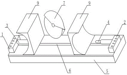
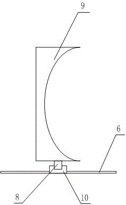
[0020] Such as figure 1 and figure 2 The shown cutting mechanism with its own clamping device includes a base 5 and a cutting mechanism 7, the cutting mechanism 7 is arranged on the rear side edge of the base 5, and the left and right ends of the upper surface of the base 5 are respectively provided with The first drive motor 1, the second drive motor 2, the output ends of the first drive motor 1 and the second drive motor 2 are respectively connected with the first electric push rod 3, the second electric push rod 4, on the base 5 The surface is also provided with a chute 6, and two sliders 10 are arranged in the chute 6, and each slider 10 is provided with a vertical rotating shaft 8, and each rotating shaft 8 is fixedly connected with a clamping Plate 9, each clamping plate 9 is that one side is a plane, and the other side is a curved surface; the cutting mechanism 7 is an electric cutter, and the cutting mechanism 7 also includes a motor and a propulsion device; the firs...

Embodiment 2

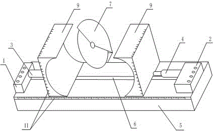
[0022] Such as image 3 In the shown cutting mechanism with its own clamping device, on the basis of Embodiment 1, the sides of the base 5 , the sides and the top surface of the clamping plate 9 are provided with scale bars 11 . The size scale bar 11 can be used to determine the specific position of the cutting place of the workpiece to be cut, so as to improve the processing accuracy.

Embodiment 3

[0024] Such as Figure 1 to Figure 3 In the shown cutting mechanism with a clamping device, on the basis of any of the above-mentioned embodiments, the chute 6 is arranged in the middle of the upper surface of the base 5, and the width of the clamping plate 9 is the same as that of the base 5 have the same width. If the chute 6 is arranged in the middle of the upper surface of the base 5, the slider 10 and the rotating shaft 8 will all be located in the middle of the entire device, ensuring symmetry and ease of use.


PUM


Abstract

The present invention discloses a cutting mechanism with a clamping device. The cutting mechanism comprises a base and a cutting mechanism. The cutting mechanism is disposed on the edge of the rear side of the base. A first drive motor is arranged at the left end of the upper surface of the base, and a second drive motor is arranged at the right end of the upper surface of the base. The output end of the first drive motor is connected with a first electric push rod, and the output end of the second drive motor is connected with a second electric push rod. A slide groove is further disposed on the upper surface of the base. Two slide blocks are disposed within the slide groove. Each slide block is provided with a vertical rotating shaft. Each rotating shaft is fixedly connected with a clamping plate. Each clamping plate comprises a flat surface and a curved surface. The present invention aims to provide the cutting mechanism with the clamping device, which solves the problem of the existing technology that the flat surface and the curved surface are difficultly simultaneously clamped by the cutter fixture for cutting, and realizes the aim of cutting the flat or curved workpieces with one set of device.

Description

technical field [0001] The invention relates to the field of mechanical cutting, in particular to a cutting mechanism with a clamping device. Background technique [0002] Cutting machine is divided into flame cutting machine, plasma cutting machine, laser cutting machine, water cutting and so on. The laser cutting machine has the fastest efficiency, the highest cutting precision, and the cutting thickness is generally small. The cutting speed of the plasma cutting machine is also very fast, and the cutting surface has a certain slope. The flame cutting machine is aimed at thicker carbon steel materials. Cutting machine applications currently include metal and non-metal industries. Generally speaking, non-metal industries are more detailed, such as stone cutting machines for cutting stones, water jetting machines, sawtooth cutting machines, lasers for cutting cloth and plastics, and chemical fiber products. Cutting machine, blade type, cutting machine, for cutting metal m...

Claims


Application Information

Patent Timeline
IPC IPC(8): B23D33/02
CPCB23D33/02
Inventor 马赟
Owner LUZHOU YUANCHENG ENG MACHINERY CO LTD
Why Eureka
Try Eureka