Transformer oil tank main body

A technology of transformer oil tank and main body, applied in the field of transformers, can solve the problems of easy damage, falling off, fixing, etc., and achieve the effects of increasing air flow speed, reducing workload, and reducing difficulty

Active Publication Date: 2021-11-02
南通兴安源金属制品有限公司
View PDF3 Cites 0 Cited by
  • Summary
  • Abstract
  • Description
  • Claims
  • Application Information

AI Technical Summary

Problems solved by technology

[0005] Aiming at the deficiencies of the prior art, the present invention provides a main body of a transformer oil tank, which solves the problem that the existing transformer needs to manually fix the cable with the hook outside the transformer during handling and processing, reduces the difficulty of handling and processing the transformer, and realizes In order to guide and move different cables in different directions, it improves the intelligence of transformer handling and processing, improves the strength of the transformer, and avoids the problem that the transformer is easily damaged and falls off when it is hit by cables

Method used


Image

  • Transformer oil tank main body
  • Transformer oil tank main body
  • Transformer oil tank main body

Examples


Embodiment 1

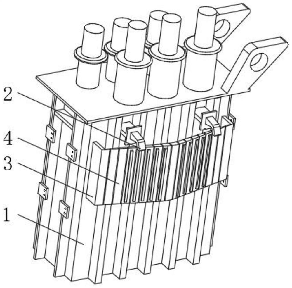
[0033] see Figure 1-3 , the present invention provides a technical solution: a main body of a transformer oil tank, including an oil tank 1, the outer side of the oil tank 1 is fixedly connected with a hook 2, both sides of the oil tank 1 are fixedly connected with an extension plate 3, and between the two sides of the extension plate 3 Settings are:

[0034] Guide device 4, the guide device 4 has a guide veneer 41, the surface of the guide veneer 41 is a magnetic metal material, one side of the guide veneer 41 is fixedly connected with an arc-shaped bump 42, and the guide veneer 41 is away from the arc-shaped bump One side of 42 is provided with an arc-shaped slot 43;

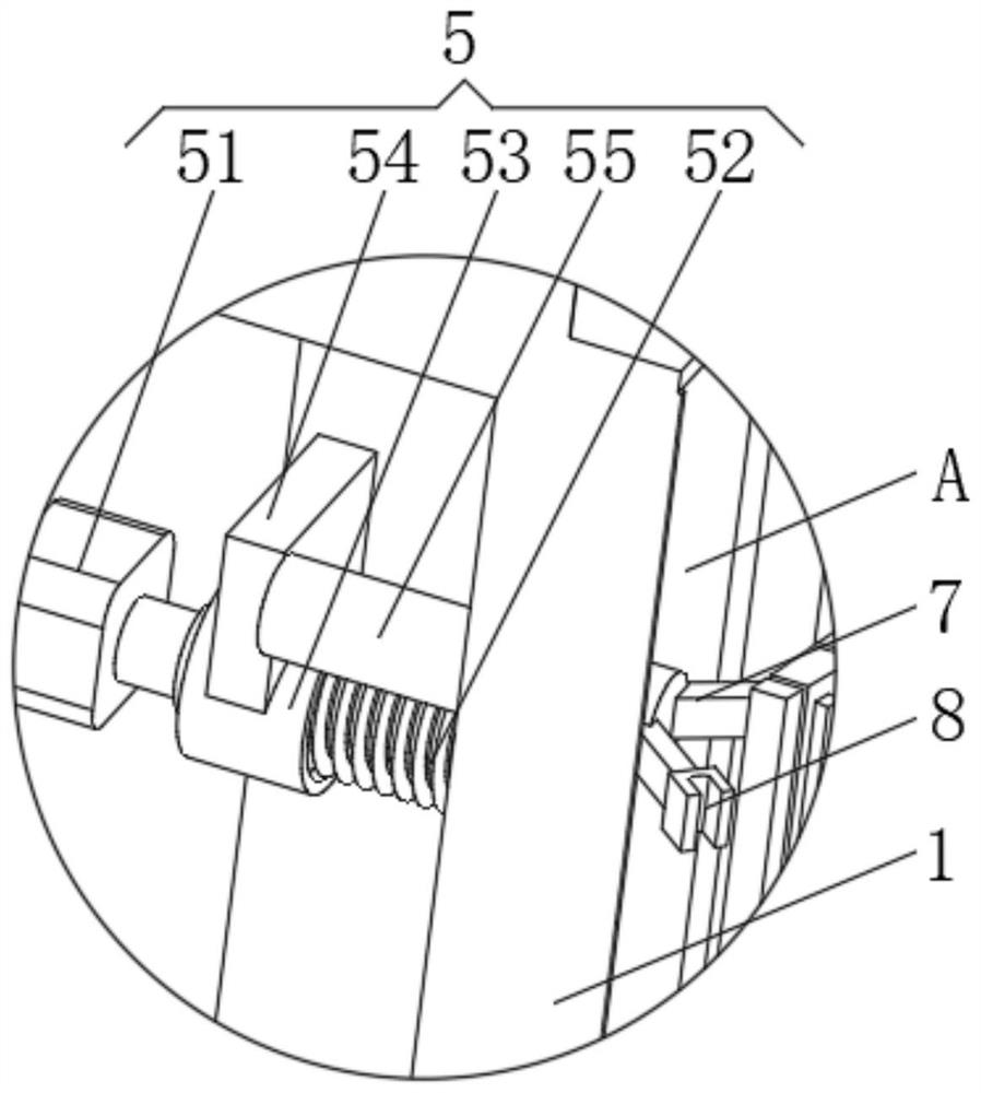
[0035]Pushing device 5, this pushing device 5 has driving motor 51, and the output end of driving motor 51 is fixedly connected with externally threaded rod 52, and the outside of externally threaded rod 52 is provided with threaded sleeve 53, and the top of threaded sleeve 53 is fixedly connected with A lo...

Embodiment 2

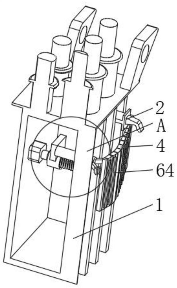
[0039] see Figure 1-6 , the present invention provides a technical solution: on the basis of Embodiment 1, a separation device 6 is provided between the two sides of the epitaxial plate 3, the separation device 6 has a separation groove 61, and the separation groove 61 runs through the guide veneer 41 and the arc One side of the inner wall of the separation groove 61 is fixedly connected with a magnet block 62, and one side of the inner wall of the separation groove 61 is fixedly connected with a buffer spring 63 near the position of the magnet block 62, and one end of the buffer spring 63 is fixedly connected with a force-bearing block 64 , the force bearing block 64 penetrates the guiding veneer 41 and extends to the outside of the guiding veneer 41 .

[0040] One end of the push rod 55 extending to the outside of the fuel tank 1 is symmetrically equipped with a swing rod 7 , the swing rod 7 is rotationally connected with the push rod 55 , and the end of the swing rod 7 awa...


PUM


Abstract

The invention discloses a transformer oil tank main body which comprises an oil tank. A hook is fixedly connected to the outer side of the oil tank, extension plates are fixedly connected to the two sides of the oil tank, a guiding device is arranged between the two sides of each extension plate, the guiding device is provided with a guiding single plate, and an arc-shaped protruding block is fixedly connected to one side of the guiding single plate; a pushing device is arranged and is provided with a driving motor; and a separating device is arranged and is provided with separating grooves. The invention relates to the technical field of transformers. According to the transformer oil tank main body, the purpose of fixing a cable and a hook outside the transformer without manual work during carrying and processing is achieved, the difficulty of carrying and processing the transformer is reduced, the purpose of directionally guiding different cables to move in different directions is achieved, the intelligent degree of carrying and processing of the transformer is improved, the strength of the transformer is improved, and the problem that the transformer is prone to being damaged and falling off when collided by the cable is solved.

Description

technical field [0001] The invention relates to the technical field of transformers, in particular to a main body of a transformer oil tank. Background technique [0002] The transformer is a device that uses the principle of electromagnetic induction to change the AC voltage. The main components are the primary coil, the secondary coil and the iron core (magnetic core). The main functions are: voltage conversion, current conversion, impedance conversion, isolation, voltage stabilization (magnetic Saturated transformers), etc., can be divided into: power transformers and special transformers (electric furnace transformers, rectifier transformers, power frequency test transformers, voltage regulators, mining transformers, audio transformers, intermediate frequency transformers, high frequency transformers, impact transformers, instrument Transformers, electronic transformers, reactors, transformers, etc.), large transformers require large lifting equipment to move due to thei...

Claims


Application Information

Patent Timeline
Patent Type & Authority Applications(China)
IPC IPC(8): H01F27/14H01F27/02H01F27/08
CPCH01F27/14H01F27/002H01F27/02H01F27/085
Inventor 梁术娟
Owner 南通兴安源金属制品有限公司
Why Eureka
Try Eureka