Suction cup glaze dipping machine

A glaze dipping machine and sucker technology, which is applied in the field of daily-use ceramics production equipment, can solve the problems of unable to meet daily production needs, complex structure of glazing device, high cost, etc., and achieve high-efficiency glazing, simple structure and high reliability. Effect

Inactive Publication Date: 2016-04-13
LISHUI UNIV
4 Cites 1 Cited by

AI-Extracted Technical Summary

Problems solved by technology

The above-mentioned glazing device has a complex structure and high cost, and can only ac...

Method used

[0018] The rotation drive mechanism includes a rotation motor 51, and a gearbox 52 connected to the output shaft of the rotation motor 51; the rotation motor 51 drives the vacuum tube 41 through the gearbox 52. The rotation driving mechanism is driven and connected with the vacuum tube 41 of the dipping assembly in the middle, and the vacuum tube 41 on the dipping assembly in the middle is connected with the vacuum tubes 41 on the dipping assembly at both ...

Abstract

The invention relates to the field of daily ceramic product production devices, in particular to a suction cup glaze dipping machine which comprises a base, a turnover shaft arranged on the base, and glaze dipping assemblies arranged on the turnover shaft. Each glaze dipping assembly comprises a vacuum pipe axially positioned on the turnover shaft, a glaze slip pipe arranged outside the vacuum pipe, a suction cup arranged at the top end of the glaze slip pipe, and a rotation drive mechanism driving the vacuum pipe to rotate, wherein a pipe opening in the upper end of the vacuum pipe is communicated with the upper end face of the suction cup, a glaze slip cavity is formed between the glaze slip pipe and the vacuum pipe, and a cavity opening in the upper end of the glaze slip cavity is communicated with the upper end face of the suction cup. The suction cup glaze dipping machine is simple in structure, to-be-processed ceramic is stably sucked through vacuum and subjected to rotating glaze dipping, glazing can be rapidly and efficiently conducted, and reliability is high.

Technology Topic

EngineeringMechanical engineering +1

Image

  • Suction cup glaze dipping machine

Examples

  • Experimental program(1)

Example Embodiment

[0015] The preferred embodiments of the present invention will be described in further detail below in conjunction with the accompanying drawings.
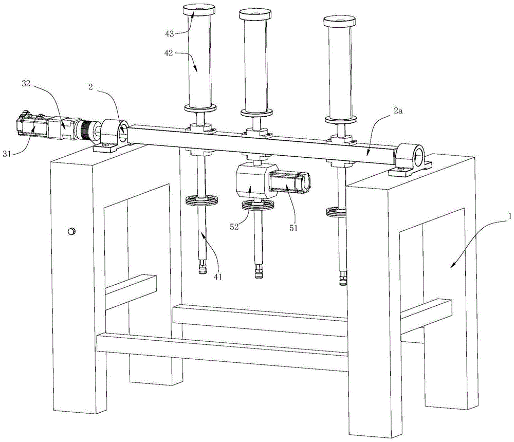
[0016] Such as figure 1 The shown suction cup glaze dipping machine includes a base 1, a turning shaft 2 arranged on the base 1, and a revolution drive mechanism that drives the turning shaft 2 to rotate, and three sets of glaze dipping assemblies arranged on the turning shaft 2 . The revolving drive mechanism includes a revolving motor 31 and a reduction box 32 connected to the output shaft of the revolving motor 31; the rotation motor is drivingly connected to the turning shaft 2 through the reduction box 32. Both ends of the turning shaft 2 are positioned on the base 1 through bearings. The turning shaft 2 between the bearings on both sides is a rectangular columnar body. The three sets of glazing assemblies are all positioned on the rectangular column 2a of the turning shaft 2 through bearings.
[0017] The three sets of glaze dipping assemblies are arranged parallel to each other. The glaze dipping assembly includes a vacuum tube 41 axially positioned on the turning shaft 2 through a bearing, a glaze slurry tube 42 arranged outside the vacuum tube 41, and a glaze slurry tube 42 The suction cup 43 at the top and the rotation drive mechanism that drives the vacuum tube 41 to rotate. The upper end of the vacuum tube 41 communicates with the upper end surface of the suction cup 43, the glaze slurry tube 42 and the vacuum tube 41 form a glaze slurry cavity, and the upper end cavity of the glaze slurry cavity communicates with the upper end surface of the suction cup 43. Specifically: the suction cup 43 has a concave ring structure in the middle, the central through hole of the suction cup 43 communicates with the upper end of the vacuum tube 41, and the suction cup 43 is provided with glazed holes that penetrate the upper and lower ends of the suction cup 43. , The glaze slurry cavity communicates with the upper end surface of the suction cup 43 through the glazing hole. Under the concave ring structure in the middle of the sucker 43, the vacuum tube 41 communicates with the through hole of the ring center of the sucker 43, and the vacuum suction force gradually increases from the periphery of the ring to the middle of the ring, which can promote the adhesion of the ceramic surface to be processed with the sucker 43 , Is conducive to the adsorption and positioning of the ceramic to be processed.
[0018] The rotation driving mechanism includes a rotation motor 51 and a gearbox 52 connected to the output shaft of the rotation motor 51; the rotation motor 51 drives the vacuum tube 41 through the gearbox 52. The rotation driving mechanism is drivingly connected with the vacuum tube 41 of the middle glaze dipping assembly, and the vacuum tube 41 on the middle glaze dipping assembly is connected with the vacuum tubes 41 on both sides of the glaze dipping assembly by belt transmission. This structure is equipped with three sets of glaze dipping assemblies and driven by the same rotation drive mechanism. On the one hand, it is beneficial to improve the efficiency of glazing, and the glazing process can be performed on three ceramics at the same time; on the other hand, it can ensure that the same batch of three ceramics is dipped The glaze time, rotation direction and speed are consistent, so that the optimal process parameters can be selected for simultaneous operation.
[0019] The suction cup 43 glaze dipping machine can be used for the automatic operation of fixed procedures for grabbing, transporting objects or operating tools, thereby replacing people's heavy labor to realize the mechanization and automation of production, and can operate in harmful environments to protect personal safety; it has a structure Simple, the ceramics to be processed can be absorbed smoothly by vacuum, and the ceramics to be processed can be dipped in rotation, which can quickly and efficiently glaze and has the advantages of high reliability. During installation, the suction cup 43 dipping machine is fixed next to the ceramic product glazing process production line, and a glaze pool is installed next to the equipment; before use, a proper amount of glaze slurry needs to be injected into the glaze slurry cavity of the glaze slurry pipe 42; The blank is positioned on the suction cup 43, and the vacuum tube 41 is connected to the vacuum generating device. The negative pressure suction generated by the vacuum tube 41 adsorbs the blank on the suction cup 43; then, control the turning shaft 2 and the glaze assembly on it to rotate to a certain angle , Until two-thirds of the green body is immersed in the glaze pool, the autorotation drive mechanism drives the green body to rotate and evenly glue the glaze slurry, and then control the turning shaft 2 and the glaze dipping assembly on it to reverse reset, and the green body continues Rotate until the glaze dipping assembly returns to the vertical position. During the tilting process of the glaze dipping assembly, the glaze slurry in the glaze slurry cavity also penetrates to the surface of the suction cup 43, and the glaze slurry is evenly coated on the bottom of the green body, that is, the green body adsorption part by rotating. When the glazing is completed, the blank selection is stopped, the external vacuum generator stops working, the negative pressure is released, and the worker can easily remove the glazed blank from the suction cup 43, which is very convenient.

PUM

no PUM

Description & Claims & Application Information

We can also present the details of the Description, Claims and Application information to help users get a comprehensive understanding of the technical details of the patent, such as background art, summary of invention, brief description of drawings, description of embodiments, and other original content. On the other hand, users can also determine the specific scope of protection of the technology through the list of claims; as well as understand the changes in the life cycle of the technology with the presentation of the patent timeline. Login to view more.

Similar technology patents

Battery disassembling device

PendingCN112290101AImprove efficiencyProtect personal safety
Owner:湖南领湃达志科技股份有限公司 +4

Data processing system and method for large-scale automobile

PendingCN113246862AImprove driving safety and convenienceProtect personal safety
Owner:上海昶音通讯科技有限公司

Safety blood sampling needle

InactiveCN109620256AProtect personal safetyavoid accidental retraction
Owner:湖州市中心血站

Safe intercept system capable of warning and obstructing over-high truck for preventing bridge collision

ActiveCN110607741AProtect personal safetyimprove security
Owner:浙江五梅开酒业有限公司

Electric tool and safe starting method

PendingCN114274085AProtect personal safetyProtection and Property Security
Owner:ZHEJIANG CROWN POWER TOOLS MFG

Classification and recommendation of technical efficacy words

  • Simple structure
  • Protect personal safety

Sharing system for air-conditioning coat

InactiveCN107440179ASimple structureeasy to wear
Owner:QINGDAO HAIER AIR CONDITIONER GENERAL CORP LTD

Feeding device of sorter of batteries plate

InactiveCN101357717ASimple structurecooperate well
Owner:NANJING NORMAL UNIVERSITY

Emergency parachuting device and method for multiple-rotor unmanned aerial vehicle

InactiveCN103895870Aavoid aircraft crashSimple structure
Owner:SOUTH CHINA AGRI UNIV +1

Quick pipe connector

Owner:YANG RICHARD

Compound coating machine achieving quantitative coating liquid supply

InactiveCN105499056Areduce pollutionProtect personal safety
Owner:XIAOGAN GUANTIAN TECH INFORMATION CONSULTING

Vehicle firing treatment method and device

InactiveCN108144220AImprove fire extinguishing efficiencyProtect personal safety
Owner:BYD CO LTD

Anti-falling safety hanging basket for aerial work

PendingCN108560896APrevent the hanging basket from fallingProtect personal safety
Owner:江苏三浦电子科技有限公司

Safety charging gun

ActiveCN109720229AGood cooling performanceProtect personal safety
Owner:东莞市东南新能源科技有限公司

Multi-functional hemispheroid safeguard product

InactiveCN104248141Aeasy to useProtect personal safety
Owner:陈春艳
Why Eureka
Try Eureka