Antitheft door

A technology for anti-theft doors and door panels is applied to anti-theft doors. field

Inactive Publication Date: 2016-04-13
CHONGQING QIANLONG DOOR IND
View PDF0 Cites 6 Cited by
  • Summary
  • Abstract
  • Description
  • Claims
  • Application Information

AI Technical Summary

Problems solved by technology

So it can't just have

Method used


Image

  • Antitheft door
  • Antitheft door
  • Antitheft door

Examples


Embodiment Construction

[0020] The present invention will be described in further detail below by means of specific embodiments:

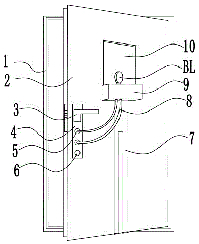
[0021] Instructions attached figure 1 The reference signs in include: door frame 1, door panel 2, door handle 3, lock plate 4, false hole 5, real hole 6, support frame 7, elastic tube 8, circuit box 9, observation window 10, hook 11, foot pad 12, rubber sleeve 13, rubber disc 14.

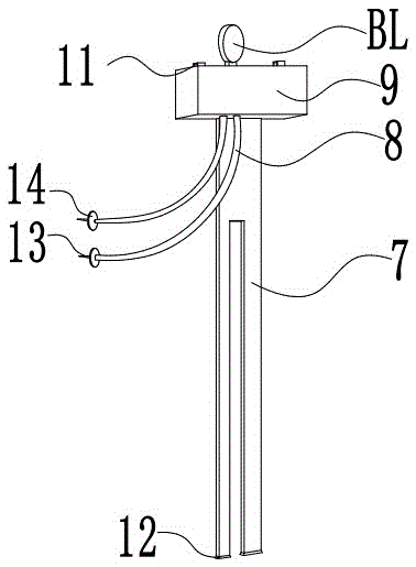
[0022] Instructions attached figure 2 The reference signs in include: support frame 7, elastic tube 8, circuit box 9, camera BL, hook 11, foot pad 12, rubber sleeve 13, rubber disc 14.

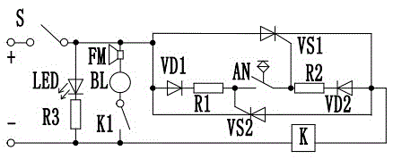
[0023] Instructions attached image 3 The reference signs in include: start switch S, light emitting diode LED, first resistor R1, second resistor R2, third resistor R3, camera BL, relay K, normally open contact K1, first diode VD1, second Two diodes VD2, first thyristor VS1, second thyristor VS2, contact switch AN, buzzer FM.

[0024] Such as figure 1 As shown, the anti-theft door includes a door frame ...


PUM


Abstract

The invention discloses an antitheft door. The antitheft door comprises a door frame, and a door board which is mounted on the door frame, wherein a lock plate is arranged on the door board, and a plurality of uniformly-distributed key holes are formed in the lock plate; each key hole comprises a true hole and a plurality of false holes; a door lock in match with the true hole is arranged on the lock plate; an alarm which is connected to all false holes is arranged on the door board, and the alarm comprises contact switches which are arranged in the false holes, relays connected to the contact switches, and a storage battery; a normally-opened contact of each relay is connected in series with a camera and a buzzer; an observing window is arranged in the door board, and the position of the camera directly faces the observing window. The antitheft door has the alarming function.

Description

technical field [0001] The invention relates to the security field, and specifically discloses an anti-theft door. Background technique [0002] Security door is the abbreviation of security door. It has both anti-theft and safety performance. According to the "General Technical Conditions for Anti-theft Safety Doors", a qualified anti-theft door cannot be pried open by ordinary hand tools such as chisels, screwdrivers, crowbars, and portable electric tools such as electric hand drills within 15 minutes or a 615 square millimeter hole can be opened on the door leaf. opening, or a 38 mm2 opening within a semicircle of 150 mm2 at the locking point. And the lock used on the security door must be the special lock for the security door with anti-drilling function after passing the test by the Testing Center of the Ministry of Public Security. Anti-theft doors can be made of different materials, but only those doors that have passed the standard inspection and received a produc...

Claims


Application Information

Patent Timeline
IPC IPC(8): E05B15/08E05B45/10E06B5/11E06B7/28E06B7/30
CPCE06B5/11E05B15/08E05B45/10E06B7/28E06B7/30
Inventor 缪文斌
Owner CHONGQING QIANLONG DOOR IND
Why Eureka
Try Eureka