A multi-frequency detecting device for detecting formation complex resistivity

A complex resistivity, detection device technology, applied in the field of multi-frequency detection devices, can solve the problems of low accuracy, narrow bandwidth, low frequency, etc., and achieve the effect of accurate evaluation

Active Publication Date: 2018-06-22
BC P INC CHINA NAT PETROLEUM CORP +1
View PDF9 Cites 0 Cited by
  • Summary
  • Abstract
  • Description
  • Claims
  • Application Information

AI Technical Summary

Problems solved by technology

[0003] Among the existing detection instruments, most electrical logging instruments use single-frequency electrical signals to collect formation information, complex resistivity logging only uses high and low frequency points for measurement, and array induction logging uses 8 different frequency points for measurement. The frequency is only designed to cooperate with multiple detection depths. The frequency is low and the bandwidth is narrow, which cannot excite the dispersion phenomenon of rocks. The detected formation information is less and the accuracy is low. Schlumberger multi-frequency dielectric scanning imaging The Dielectric Scanner only uses the real part information of the resistivity, but cannot accurately measure the complex resistivity parameters, so it is difficult to obtain the rock resistivity dispersion curve, and then it is difficult to predict the saturation of the rock

Method used


Image

  • A multi-frequency detecting device for detecting formation complex resistivity
  • A multi-frequency detecting device for detecting formation complex resistivity
  • A multi-frequency detecting device for detecting formation complex resistivity

Examples


Embodiment Construction

[0025] The following will clearly and completely describe the technical solutions in the embodiments of the present invention with reference to the accompanying drawings in the embodiments of the present invention. Obviously, the described embodiments are only some, not all, embodiments of the present invention. Based on the embodiments of the present invention, all other embodiments obtained by persons of ordinary skill in the art without making creative efforts belong to the protection scope of the present invention.

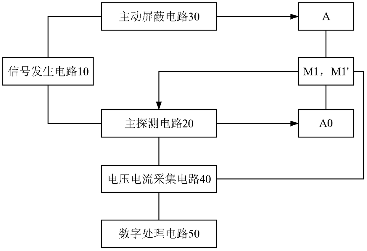
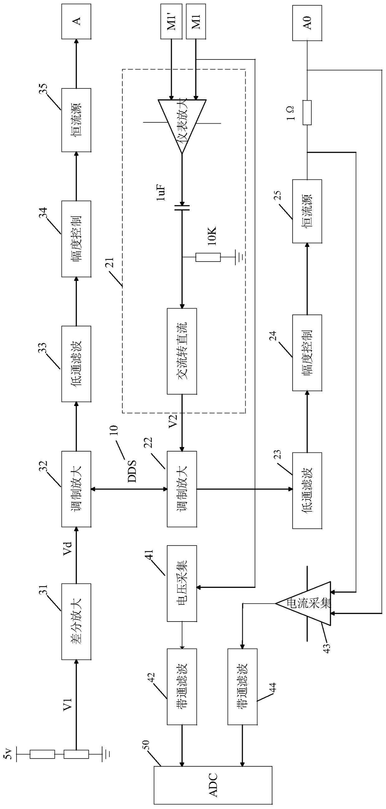
[0026] A multi-frequency detecting device for detecting formation complex resistivity according to an embodiment of the present invention will be described below with reference to the accompanying drawings.

[0027] Embodiments of the present invention use a detector with a coil system to detect the formation. The coil system includes a receiving coil and a transmitting coil. A detection signal of a certain frequency or several frequencies is transmitted, and ...


PUM


Abstract

The invention provides a multi-frequency detection device for detecting stratum complex resistivity. The device comprises a shielding electrode, a main detecting electrode, two monitoring electrodes, a signal generating circuit, an active shielding circuit, a main detecting circuit, a voltage and current collection circuit and a digital processing circuit; the two monitoring electrodes are arranged between the shielding electrode and the main detecting electrode, the signal generating circuit is used for producing a square wave signal, needed by detection, of preset detection frequency, the active shielding circuit is used for generating a shielding signal to the shielding electrode according to the square wave signal, the main detecting circuit is used for generating a detecting signal which has the same frequency and phase position as those of the shielding signal according to the potential difference of the monitoring electrodes and the square wave signal and outputting the detecting signal to the main detecting detection, the voltage and current collection circuit is used for detecting electric potentials of the monitoring electrodes and a current in the main detecting electrode, the digital processing circuit is used for conducting waveform analysis and treatment on a voltage signal and a current signal, and a stratum complex resistivity frequency spectrum is obtained through calculation. The multi-frequency detection device for detecting the stratum complex resistivity can produce multiple frequency signals, and the stratum complex resistivity frequency spectrum is accurately measured.

Description

technical field [0001] The invention relates to the scientific and technical field of geophysical logging instruments, in particular to a multi-frequency detection device for detecting formation complex resistivity. Background technique [0002] According to the long-term experimental research on the physical properties of rocks, it is found that the electrical parameters of rocks (such as resistivity, dielectric constant) have dispersion phenomena, and the dispersion parameters have a good correspondence with the water saturation of rocks. The complex number of parameters contains rich rock information, which can be used to better detect oil and gas and distinguish oil and water layers. [0003] Among the existing detection instruments, most electrical logging instruments use single-frequency electrical signals to collect formation information, complex resistivity logging only uses high and low frequency points for measurement, and array induction logging uses 8 different f...

Claims


Application Information

Patent Timeline
Patent Type & Authority Patents(China)
IPC IPC(8): E21B49/00
CPCE21B49/087
Inventor 柯式镇姜明
Owner BC P INC CHINA NAT PETROLEUM CORP
Why Eureka
Try Eureka