
Vibration reduction structure applied to rocket tail end acoustic self-conduction array

A vibration-damping structure and sound-based array technology, applied in the direction of shock absorbers, spring/shock absorber design features, shock absorbers, etc., can solve the problem of interference sound-based arrays receiving target echo signals, reduced self-guiding accuracy, and inability Target tracking and positioning

Active Publication Date: 2016-04-13
710TH RES INST OF CHINA SHIPBUILDING IND CORP
View PDF9 Cites 0 Cited by
  • Summary
  • Abstract
  • Description
  • Claims
  • Application Information

AI Technical Summary

Problems solved by technology

During the propulsion process of the rocket engine, the propulsion noise and vibration noise generated seriously interfere with the acoustic matrix receiving the target echo signal, seriously reducing the homing accuracy, and even making it impossible to track and locate the target

Method used


Image

  • Vibration reduction structure applied to rocket tail end acoustic self-conduction array
  • Vibration reduction structure applied to rocket tail end acoustic self-conduction array
  • Vibration reduction structure applied to rocket tail end acoustic self-conduction array

Examples


Embodiment Construction

[0018] The present invention will be described in detail below with reference to the accompanying drawings and embodiments.

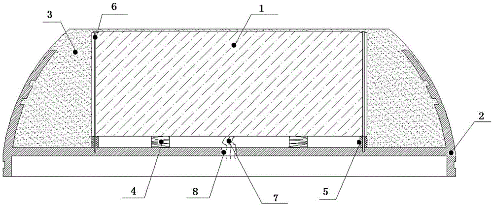
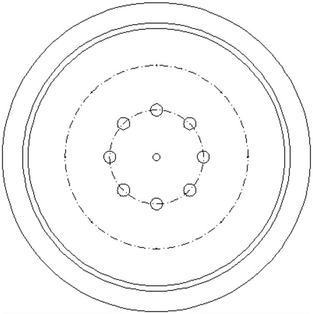
[0019] as attached figure 1 and 2 As shown, the present invention provides a vibration damping structure applied to the acoustic self-guided array at the end of a rocket. The vibration damping structure includes an acoustic base unit 1, a base 2, a vibration isolation rubber 3, a compression spring 4, and a sealing gasket 5. and screw 6;

[0020] Eight threaded holes matched with the screw 6 are processed on the bottom surface of the base 2;

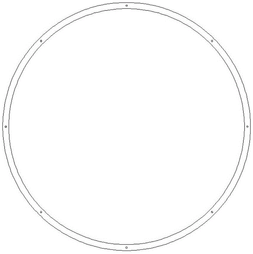
[0021] The acoustic array unit 1 and the sealing washer 5 are both machined with eight via holes, and the positions of the via holes correspond to the positions of the threaded holes on the bottom surface of the base 2. The shape and structure of the sealing washer 5 is shown in the appendix. image 3 shown;

[0022] The screw 6 restricts the acoustic base array unit on the inner surface of the base after pass...


PUM


Abstract

The invention provides a vibration reduction structure applied to a rocket tail end acoustic self-conduction array, and belongs to the technical field of acoustic array vibration reduction structural designing. The vibration reduction structure comprises an acoustic base unit, a base, vibration isolation rubber, compression springs, a sealing gasket and threaded rods. After the threaded rods penetrate through through holes formed in the acoustic base unit and the sealing gasket, an acoustic array unit is limited by the threaded rods on the inner surface of the base, and the sealing gasket guarantees that the interior of a sealed portion is in a sealed state. The compression springs are located between the bottom surface of the acoustic base unit and the inner surface of the base, and are in a compressed state, and the acoustic base unit has axial movement in the axial direction of the threaded rods. An outgoing line of the acoustic base unit goes out of a line through hole formed in the base. The vibration isolation rubber is arranged in the portion between the base and the acoustic array unit in a filled mode, so that sealing of the whole acoustic base unit is achieved. According to the invention, the purpose of reducing the influence of vibration noise of a rocket system on the working performance of the acoustic self-conduction array is achieved in a mode of horizontal and longitudinal united vibration reduction.

Description

technical field [0001] The invention relates to an acoustic self-guided basic array in the rocket-assisted precision guidance technology, in particular to the vibration reduction structure design of an acoustic self-guided basic array, and belongs to the technical field of acoustic self-guided array vibration reduction structure design. Background technique [0002] Rocket terminal acoustic self-guided technology is the key technology in rocket-assisted precision guidance technology. During the propulsion process of the rocket engine, the propulsion noise and vibration noise generated by the rocket engine seriously interfere with the reception of the target echo signal by the acoustic array, which seriously reduces the self-guided accuracy, and even cannot track and locate the target. Therefore, it is particularly important to add a vibration and noise reduction structure between the acoustic array unit and the carrier. SUMMARY OF THE INVENTION [0003] In view of this, t...

Claims


Application Information

Patent Timeline
Patent Type & Authority Applications(China)
IPC IPC(8): F16F7/00
CPCF16F7/00F16F2230/30
Inventor 赵鹏涛张恒汪小亚曹振宇汶宏刚
Owner 710TH RES INST OF CHINA SHIPBUILDING IND CORP
Learn More