Tensioning or guide rail having a continuous recessed sliding body

A technology for guiding rails and sliding bodies, applied in the direction of transmission devices, belts/chains/gears, mechanical equipment, etc., can solve the problems of transmission chain manufacturing tolerances, elongation, etc., and achieve the effect of reducing noise generation

Inactive Publication Date: 2016-04-13
IWIS MOTORSYSTEME GMBH & CO KG
View PDF11 Cites 6 Cited by
  • Summary
  • Abstract
  • Description
  • Claims
  • Application Information

AI Technical Summary

Problems solved by technology

In addition, manufacturing tolerances and elongations of the drive chain o...

Method used


Image

  • Tensioning or guide rail having a continuous recessed sliding body
  • Tensioning or guide rail having a continuous recessed sliding body
  • Tensioning or guide rail having a continuous recessed sliding body

Examples


Embodiment Construction

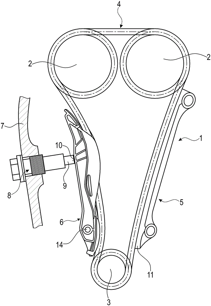
[0017] exist figure 1 A timing chain drive 1 for an internal combustion engine, shown schematically in , comprises two upper camshaft sprockets 2, a lower crankshaft sprocket 3, an endless drive or timing chain 4 wound around said sprockets, for timing A conventional guide rail 5 that guides the timing chain 4 in the tensioned span of the timing chain drive 1 and a pivotally arranged tensioner that presses against the timing chain 4 in the slack span of the timing chain drive 1 Track 6. The tensioning rail 6 is pressed against the timing chain 4 by a tensioning device 8 provided in the engine hood 7 . The tensioning device 8 is here preferably configured as a hydraulically operated chain tensioner, which is connected to the engine oil hydraulics, so that the tensioning piston 9 of the tensioning device 8 presses against the pivotally arranged tensioning rail 6 Press area 10. The conventionally designed guide rail 5 rests with its sliding contact surface of the sliding body ...


PUM


Abstract

The invention provdies a tensioning or guide rail having a continuous recessed sliding body. A tensioning or guide rail for a drive chain, in particular for a chain drive of an internal combustion engine, comprises a carrier body with at least two chain guide sections and with at least one recessed section. The at least one recessed section is arranged between two chain guide sections and recessed relative to a tangent connecting the adjoining chain guide sections, the at least two chain guide sections having each a sliding-contact surface for contacting the drive chain. A continuous sliding body is arranged on the carrier body along the at least two chain guide sections and the at least one recessed section, the sliding body defining the sliding-contact surfaces of the at least two chain guide sections and a surface of the at least one recessed section, the surface facing the drive chain.

Description

technical field [0001] The invention relates to a tensioning or guide rail for a drive chain, in particular for a chain drive of an internal combustion engine, comprising: having at least two chain guide segments and having at least one recessed area A carrier for segments, the at least one recessed segment is disposed between two chain guide segments and is recessed relative to a tangent connecting adjacent chain guide segments, and the at least two chain guide segments each have Sliding contact surface for contacting drive chains. Furthermore, the invention relates to a chain drive comprising such a tensioning or guiding track. Background technique [0002] In the case of chain drives it is very common to use tensioning devices comprising a chain tensioner and tensioning and guiding rails. However, a preferred field of application is use in internal combustion engines, in which the timing chain drive drives the camshaft by means of a timing chain. In this field of appli...

Claims


Application Information

Patent Timeline
IPC IPC(8): F16H7/08
CPCF16H7/08F16H7/18F16H2007/0812F16H2007/0872F16H2007/0893F16H2007/185
Inventor H.盖贝尔R.佩里西诺托
Owner IWIS MOTORSYSTEME GMBH & CO KG
Why Eureka
Try Eureka