Fluid circuit breakage protector

A protector and fluid technology, applied to valve details, safety valves, engine components, etc., can solve problems such as property loss and achieve precise fluid control

Active Publication Date: 2016-04-13
NANJING FANSKI IND
View PDF7 Cites 1 Cited by
  • Summary
  • Abstract
  • Description
  • Claims
  • Application Information

AI Technical Summary

Problems solved by technology

[0002] The existing open water supply will cause large property losses after leakage, so a device is urgently needed to reduce the loss caused by the leakage of open water supply

Method used


Image

  • Fluid circuit breakage protector

Examples


Embodiment Construction

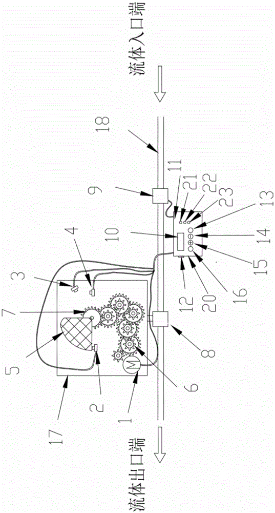
[0011] The present invention will be further described below in conjunction with accompanying drawing:

[0012] Such as figure 1 , a fluid circuit breaker, comprising a water inlet pipe 18, a flow sensor 9, a valve 8, a valve electric actuator 17 and a control terminal 20, the flow sensor 9 and the water inlet pipe 18 are connected by threads, and the flow sensor 9 and the The control terminal 20 is electrically connected, the valve 8 is threaded to the water inlet pipe 18, the water inlet pipe 8 is nested connected to the valve electric actuator 17, the valve electric actuator 17 is connected to the control terminal 20 by wires; the valve electric actuator 17 is fixed to the valve 8 Connection, the center rod of gear 7 is concentrically nested with the control rod of valve 8, the center rod of gear 7 is also fixedly connected with the fan-shaped control block 5, the drive motor 1 is connected with the gear set 6 through gear transmission, the drive motor 1 and the flow sensor...


PUM


Abstract

The invention discloses a fluid circuit breakage protector. The fluid circuit breakage protector is characterized by comprising a water inlet tube (18), a flow inductor (9), a valve (8), a valve electric actuator (17) and a control terminal (20), wherein the flow inductor (9) and the water inlet tube (18) are connected by threads; the flow inductor (9) is electrically connected to a control terminal (20) through a wire; the valve (8) and the water inlet tube (18) are in threaded connection; the water inlet tube (8) and the valve electric actuator (17) are in nested connection; and the valve electric actuator (17) is connected to a control terminal (20) through an electric wire. According to the fluid circuit breakage protector disclosed by the invention, the control panel and the control terminal can be in fixed power line connection, and can also be separately arranged but in wireless connection for fluid cut-off operation.

Description

technical field [0001] The invention relates to a fluid circuit breaker. Background technique [0002] Existing open water supply will cause greater property loss after leakage, so a device is urgently needed to reduce the loss caused by the leakage of open water supply. Contents of the invention [0003] The object of the present invention is to provide a fluid circuit breaker, which is sensitive to water flow and can effectively reduce waste caused by leakage. [0004] Technical scheme of the present invention is: [0005] A fluid circuit breaker, comprising a water inlet pipe, a flow sensor, a valve, an electric valve actuator and a control terminal, the flow sensor is connected to the water inlet pipe through threads, the flow sensor is electrically connected to the control terminal, and the valve is connected to the inlet The water pipe is threadedly connected, the water inlet pipe is nested with the valve electric actuator, the valve electric actuator is connected ...

Claims


Application Information

Patent Timeline
Patent Type & Authority Applications(China)
IPC IPC(8): F16K17/36F16K37/00F16K31/04F16K31/53
CPCF16K17/36F16K31/046F16K31/047F16K31/53F16K37/0091
Inventor 刘文东杨贺
Owner NANJING FANSKI IND
Why Eureka
Try Eureka