Multi-freedom-degree drill rod lubricating oscillation rod

A swing rod and degree of freedom technology, applied in the direction of lubricating parts, engine lubrication, engine components, etc., can solve problems such as breakage, uneven lubrication, deformation, etc., and achieve the effect of saving production costs, not easy to wear, and evenly applied

Active Publication Date: 2016-04-13
ZHEJIANG KAISHAN HEAVY IND CO LTD
View PDF4 Cites 0 Cited by
  • Summary
  • Abstract
  • Description
  • Claims
  • Application Information

AI Technical Summary

Problems solved by technology

There are following deficiencies in the existing drilling rod lubricating device: 1. The lubricating device (hereinafter referred to as the lubricating device) used to apply lubricating butter for the drilling rod is usually a rigid structure, which is easy to deviate from the set position when encountering external resistance, so that The joint with the drill pipe is not enough, and the lubrication is uneven; 2. The lubricating device is usually a rigid structure. When the external resistance is too large, it will be damaged or deformed; 3. The oil nozzle of the lubricating device is attached to the drill pipe, and the drill When the rod is loaded and unloaded, it will move in the vertical direction, so that the fitting surface between the oil nipple and the drill pipe is easy to wear, resulting in insufficient fit between it and the drill pipe

Method used


Image

  • Multi-freedom-degree drill rod lubricating oscillation rod
  • Multi-freedom-degree drill rod lubricating oscillation rod

Examples


Embodiment Construction

[0012] Below in conjunction with accompanying drawing this patent is described further.

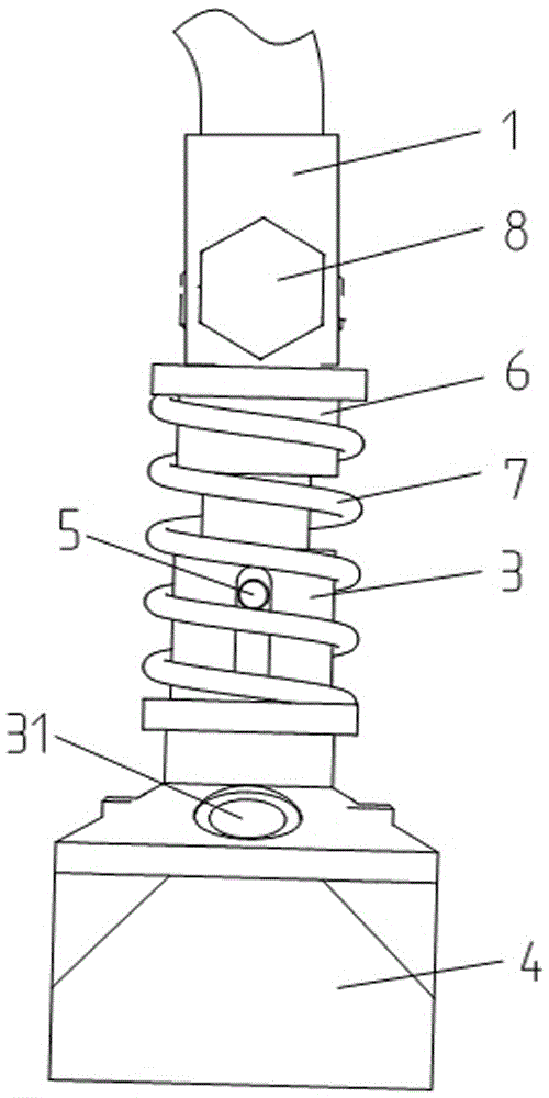
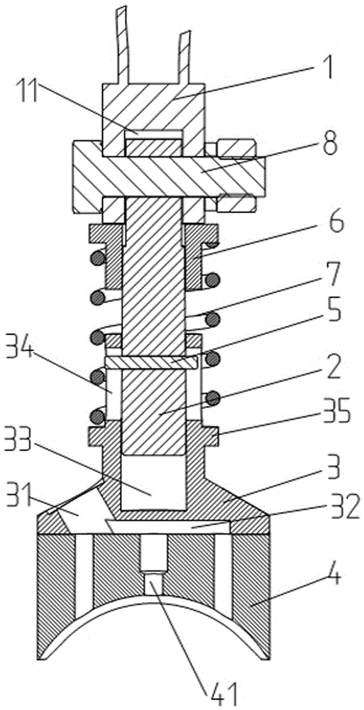
[0013] like figure 1 and figure 2 The shown multi-degree-of-freedom drill pipe lubricating swing rod includes a support tube 1, a rotating shaft 2, a nozzle socket 3 and a nozzle 4. The nozzle 4 is made of a wear-resistant material, and the front end of the nozzle 4 In order to fit the curved surface of the drill pipe surface, the oil nozzle 4 is provided with a number of oil injection holes 41 evenly distributed in the width and height directions of the oil nozzle 4. The fuel injection hole A, the fuel injection hole B and the fuel injection hole C located on the left and right sides of the fuel injection hole A, the fuel injection hole B, the fuel injection hole A and the fuel injection hole C are evenly distributed in the width direction of the oil nozzle 4 . The oil nozzle 4 is detachably installed on the front end of the oil nozzle socket 3 through bolts. Compared with the existi...


PUM


Abstract

The invention discloses a multi-freedom-degree drill rod lubricating oscillation rod. The oscillation rod comprises a supporting pipe, a rotating shaft, an oil pumping nozzle connecting base and an oil pumping nozzle. A plurality of oil spraying holes uniformly distributed in the width and height direction of the oil pumping nozzle are formed in the oil pumping nozzle. The oil pumping nozzle is detachably installed at the front end of the oil pumping nozzle connecting base. An oil injection hole for being connected with an oil injection pipe and a communicating cavity communicated with the oil injection hole are formed in the oil pumping nozzle connecting base. The oil injection hole is communicated with all the oil spraying holes through the communicating cavity. A fixing groove A is formed in the rear end of the oil pumping nozzle connecting base. The front end of the rotating shaft is connected to the fixing groove A in a sleeved mode. The rotating shaft and the fixing groove A can relatively move in the radial direction and constrain the motion stroke through a limiting plug pin. The rear end of the rotating shaft is fixed to the front end of the supporting pipe. The rotating shaft can rotate in the axial direction. An outer ring of the rotating shaft is sleeved with a spring. Lubricating butter is smeared more uniformly, and when the external resistance is excessively large, the rotating shaft can drive the oil pumping nozzle to rotate, and the self-protection effect is achieved.

Description

technical field [0001] The invention relates to a device for lubricating drill rods of mine drilling equipment, in particular to a multi-degree-of-freedom drill rod lubricating swing rod. Background technique [0002] The drill pipe thread of the engineering drilling rig is socketed on the trolley. When loading and unloading the drill pipe, in order to facilitate disassembly and protect the connecting thread of the drill pipe, it is necessary to apply butter to the thread connection. There are following deficiencies in the existing drilling rod lubricating device: 1. The lubricating device (hereinafter referred to as the lubricating device) used to apply lubricating butter for the drilling rod is usually a rigid structure, which is easy to deviate from the set position when encountering external resistance, so that The joint with the drill pipe is not enough, and the lubrication is uneven; 2. The lubricating device is usually a rigid structure. When the external resistance i...

Claims


Application Information

Patent Timeline
Patent Type & Authority Applications(China)
IPC IPC(8): F16N21/00F16N21/02
CPCF16N21/00F16N21/02
Inventor 夏剑辉徐雪锋舒慧建李勇涛杜标吴海林
Owner ZHEJIANG KAISHAN HEAVY IND CO LTD
Why Eureka
Try Eureka