Railway vehicle axle phased array ultrasonic flaw detection platform

An ultrasonic flaw detection and rail vehicle technology, which is applied in the analysis of solids using sonic/ultrasonic/infrasonic waves, can solve the problems of large number, prone to missed inspections, cumbersome processes, etc., and achieves a high degree of automation, coverage, and high detection accuracy. Effect

Active Publication Date: 2016-04-13
JILIN UNIV
View PDF10 Cites 7 Cited by
  • Summary
  • Abstract
  • Description
  • Claims
  • Application Information

AI Technical Summary

Problems solved by technology

The traditional method of ultrasonic flaw detection of axles is to arrange multiple ordinary straight probes or oblique probes with different angles at different positions on the end face and side of the axle. Occurrence of missed detection; in recent years, some other ultrasonic flaw detection platforms have also appeared. For example, in order to meet the requirements of shaft sections with different diameters, multiple probes with different radians are installed on a probe bracket. During detection, the probe follows the probe bracket along the axle bus When detecting shaft sections with different diameters, just extend the corresponding probes. Compared with the traditional method, this flaw detection platform has a higher degree of automation and greatly improves the detection efficiency. However, it still requires multiple sets of probes. Axles cannot be used universally
[0003] Chinese patent CN103760237A discloses a hollow shaft ultrasonic flaw detection device, which adopts a push-pull rod structure, and the probe is inserted into the hole of the hollow shaft for flaw detection. This type of method is only suitable for hollow shafts. Hollow shafts are also available as solid shafts, so not all are suitable
Chinese patent CN202870036U discloses a phased array ultrasonic testing device for solid axles. Phased array ultrasonic probes are arranged on the axle end face and the axle neck respectively, which makes it difficult to achieve full coverage of sound waves, and needs to be redesigned for axles of different specifications. The location of the probe is poor in versatility

Method used


Image

  • Railway vehicle axle phased array ultrasonic flaw detection platform
  • Railway vehicle axle phased array ultrasonic flaw detection platform
  • Railway vehicle axle phased array ultrasonic flaw detection platform

Examples


Embodiment Construction

[0033] The technical solutions of the present invention will be described in further detail below through the accompanying drawings and embodiments.

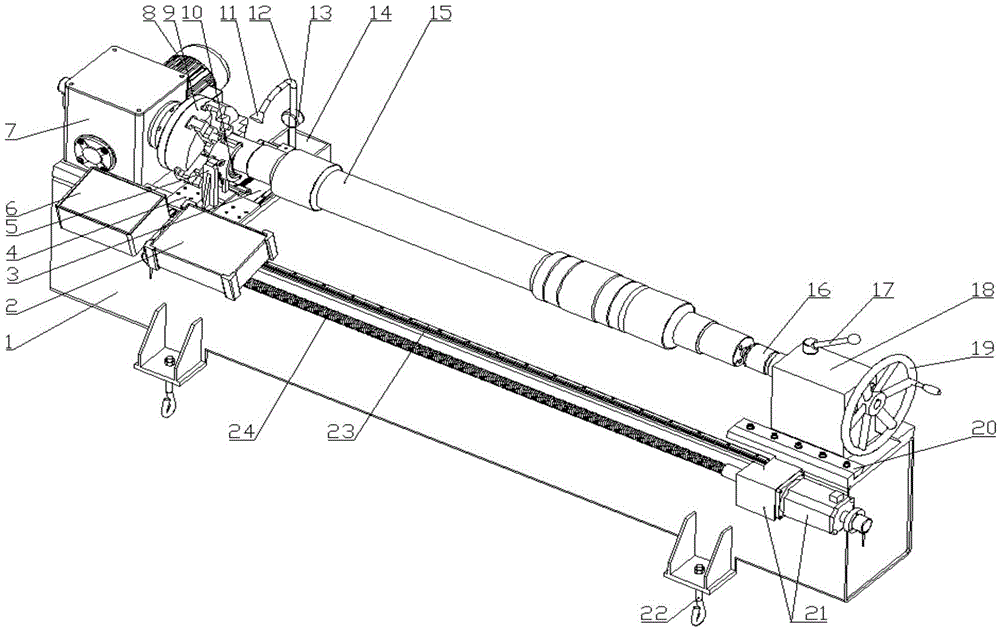
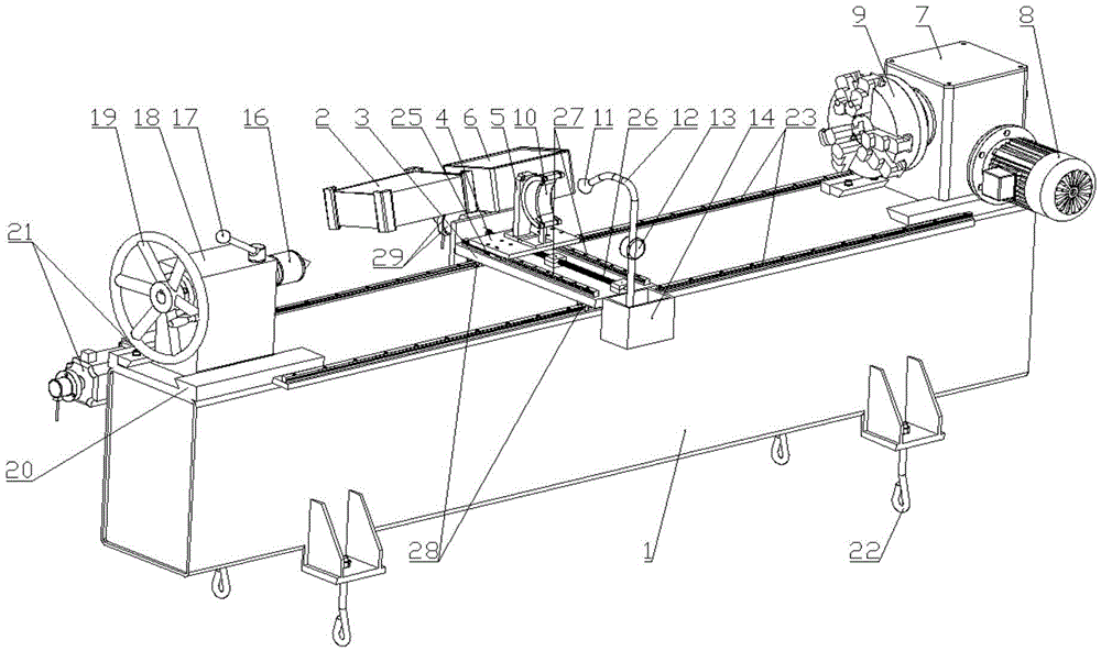
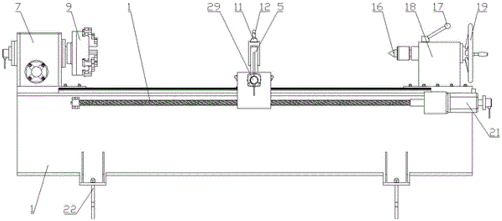
[0034] Such as figure 1 , figure 2 , image 3 , Figure 4 with Figure 7 As shown, the present invention discloses a rail vehicle axle phased array ultrasonic flaw detection platform, including a bed 1, an axle clamping device, a spindle drive transmission mechanism, a detection mechanism, a coupling agent spraying device, a control mechanism, and a phased array flaw detector 2 and related connectors;

[0035] The bed 1 is used as the basis for the installation and acceptance of the rest of the components. It adopts an angle steel frame, and its main body surface is made of steel plates, and is fixed on the ground with anchor bolts 22;

[0036] Such as Image 6 As shown, the spindle drive transmission mechanism includes a spindle motor 8 fixed on the bed 1 and a spindle worm gear reducer 7 for driving the axle to be teste...


PUM


Abstract

The invention discloses a railway vehicle axle phased array ultrasonic flaw detection platform. The railway vehicle axle phased array ultrasonic flaw detection platform comprises a lathe bed, an axle clamping device, s spindle drive transmission mechanism, a detection mechanism, a coupling agent spraying device, a control mechanism and a phased array flaw detector, wherein the detection mechanism can enable a phased array probe to move along the axial direction and the radial direction of a to-be-detected axle under the driving of an axial detection component and a radial detection component according to the control of a controller, so as to realize ultrasonic flaw detection on axle segments with different lengths and diameters. The flaw detection platform provided by the invention can perform comprehensive and automatic flaw detection on solid axles and hollow axles of various specifications of current railway vehicles, the flaw detection speed is fast, the automation degree is high, the coverage range is comprehensive, and a higher detection degree is realized.

Description

technical field [0001] The invention relates to a detection platform, in particular to a rail vehicle axle phased array ultrasonic flaw detection platform, which belongs to the field of non-destructive testing. Background technique [0002] The axle is the key stress-bearing part of the running parts of the rail vehicle. It not only bears the load from the car body (the traction force and braking force applied during the running), but also bears the additional load caused by the unevenness of the track. It is a complicated force Parts, therefore, the axle is prone to fatigue damage and other damage. The national standard also stipulates that when the rail vehicle travels for a certain mileage, ultrasonic flaw detection should be performed on the axle. The traditional method of ultrasonic flaw detection of axles is to arrange multiple ordinary straight probes or oblique probes with different angles at different positions on the end face and side of the axle. Occurrence of m...

Claims


Application Information

Patent Timeline
Patent Type & Authority Applications(China)
IPC IPC(8): G01N29/06
CPCG01N29/06
Inventor 刘玉梅苏建葛琦张宏涛郭艳秀熊明烨乔宁国刘绪洪李战伦陈云徐观张立斌潘洪达陈熔戴建国林惠英
Owner JILIN UNIV
Why Eureka
Try Eureka