Holographic optical waveguide and holographic optical waveguide display device

A technology of optical waveguide and flat optical waveguide, which is applied in the direction of light guide, optics, optical components, etc., can solve the problems of low diffraction rate of holographic grating, inability to suppress zero-order wave, and difficult separation of conjugate images, so as to achieve high diffraction efficiency and reduce Difficult design and production, simple production process

Inactive Publication Date: 2016-04-13
SOUTHEAST UNIV
View PDF4 Cites 37 Cited by
  • Summary
  • Abstract
  • Description
  • Claims
  • Application Information

AI Technical Summary

Problems solved by technology

Due to the low diffraction rate of the holographic grating used in the traditional holographic optical waveguide display technology, the coupling in and out of light waves will be accompanied by energy loss, and at the same time, the zero-order wave cannot be suppressed, and the conjugate images are difficult to separate

Method used


Image

  • Holographic optical waveguide and holographic optical waveguide display device
  • Holographic optical waveguide and holographic optical waveguide display device
  • Holographic optical waveguide and holographic optical waveguide display device

Examples


Embodiment Construction

[0029] The technical scheme of the present invention is described in detail below in conjunction with accompanying drawing:

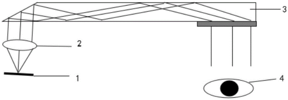
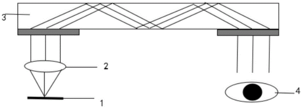
[0030] The basic structure of the holographic optical waveguide of the present invention is similar to that of the prior art, including a slab optical waveguide and an optical coupling end and an optical coupling end respectively arranged at both ends of the slab optical waveguide; the optical coupling end reflects the received light , so that the reflected light satisfies the total reflection condition, and after multiple total reflections between the two reflective surfaces of the flat optical waveguide, it is transmitted to the optical coupling end, and the optical coupling end diffracts the received light; the optical coupling The output end is a holographic grating. In order to improve the diffraction efficiency of the holographic grating, the present invention uses the polarization holographic liquid crystal grating as the optical coupling end of ...


PUM


Abstract

The invention discloses a holographic optical waveguide, and belongs to the technical field of augmented reality and virtual reality. The holographic optical waveguide comprises a planar optical waveguide, and an optical coupling in end and an optical coupling out end which are respectively arranged at the two ends of the planar optical waveguide. The optical coupling in end reflects received light rays so that the reflected light rays are enabled to meet the total reflection conditions to be transmitted to the optical coupling out end through multiple times of total reflection between the two reflecting surfaces of the planar optical waveguide. The received light rays are diffractively emergent out of the optical coupling out end. The optical coupling out end is a holographic grating. The holographic grating is a polarization holographic liquid crystal grating comprising a transparent substrate, a light orientation layer and a liquid crystal layer which are arranged in turn, wherein polarization holographic patterns having periodic structures are recorded on the light orientation layer. The invention also discloses a holographic optical waveguide display device. The polarization holographic liquid crystal grating is used as the optical coupling out end of the holographic optical waveguide so that 100% of diffraction efficiency can be achieved theoretically, and zero order waves can be suppressed and conjugate images can be eliminated.

Description

technical field [0001] The invention relates to a holographic optical waveguide and a holographic optical waveguide display device, belonging to the technical fields of augmented reality and virtual reality. Background technique [0002] Optical waveguide display technology for augmented reality and virtual reality has become a key research direction in the display field in recent years, and it is widely used in the head-up display market, such as the head-up display on cars and the head-up display on airplanes. Optical waveguide display is a comprehensive system engineering with high technical content covering and involving multiple disciplines, and optoelectronic technology occupies a pivotal position, including: image source and optical system design technology, tracking technology, quick disconnection technology, etc. Among them, the design of the optical system is the key to the optical waveguide display technology, which requires high display efficiency, low power cons...

Claims


Application Information

Patent Timeline
Patent Type & Authority Applications(China)
IPC IPC(8): G02B6/122G02B27/01G02B5/32
CPCG02B6/122G02B5/32G02B27/0103G02B2027/0105
Inventor 夏军刘硕硕
Owner SOUTHEAST UNIV
Why Eureka
Try Eureka