UUV adaptive fuzzy sliding-mode control method under strong disturbance of load arranging

A technology of adaptive fuzzy and control methods, applied in the direction of adaptive control, general control system, control/adjustment system, etc., can solve problems such as UUV damage, large jitter, and unsatisfactory effects, so as to avoid damage and reduce jitter vibration effect

Active Publication Date: 2016-04-13
HARBIN ENG UNIV
View PDF5 Cites 9 Cited by
  • Summary
  • Abstract
  • Description
  • Claims
  • Application Information

AI Technical Summary

Problems solved by technology

[0003] The control under the strong disturbance of UUV load placement is nonlinear and very complicated, and the sliding mode control is very suitable for the applica

Method used


Image

  • UUV adaptive fuzzy sliding-mode control method under strong disturbance of load arranging
  • UUV adaptive fuzzy sliding-mode control method under strong disturbance of load arranging
  • UUV adaptive fuzzy sliding-mode control method under strong disturbance of load arranging

Examples


specific Embodiment approach 1

[0024] Embodiment 1: A UUV adaptive fuzzy sliding mode control method under strong disturbance of load placement includes the following steps:

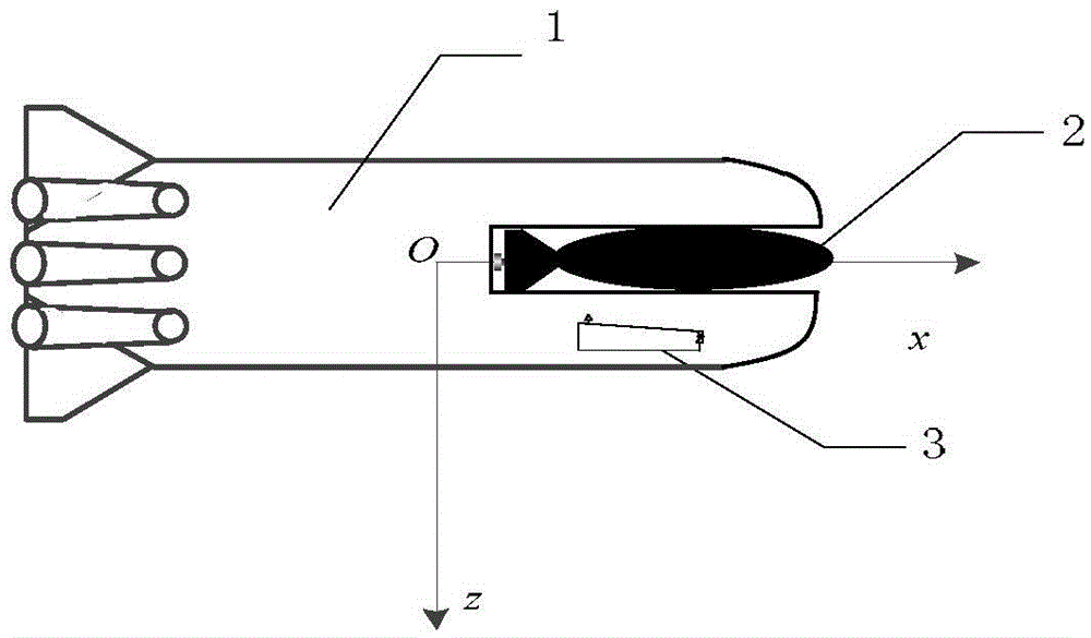
[0025] Step 1: The UUV carries out the load deployment, which produces two kinds of interference to the UUV, one is the interference caused by the movement of the load in the grid-shaped tube, and the other is the interference caused by the water entering the water supply tank;

[0026] Step 2: Obtain the current state μ of the UUV, and construct a dynamic model of the UUV under load deployment disturbance;

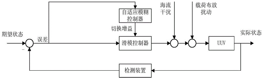
[0027] Step 3: Design the sliding mode surface s according to Step 2, and construct the sliding mode controller;

[0028] Step 4: Design a fuzzy controller based on the sliding mode controller constructed in step 3. The input of the fuzzy controller is the sliding mode surface s, and the output is △K, and the △K is the increment of the switching control law coefficient of the sliding mode controller value;

[0029] Step 5: Use ...

specific Embodiment approach 2

[0033] Specific embodiment 2: The difference between this embodiment and specific embodiment 1 is that in the step 1, the UUV carries out load deployment, and two types of interference are generated on the UUV, specifically:

[0034] (1) The movement of the load in the grid-shaped tube causes interference;

[0035] The motion equation of the load in the grid tube is:

[0036] ( m T + λ 11 ) dv T d t = F T - R x - F m - - - ( 1 )

[0037] where the m T is the load mass, v T is the moving speed of the load in the tube, λ 11 is the additional mass of the l...

specific Embodiment approach 3

[0071] Embodiment 3: This embodiment differs from Embodiment 1 or Embodiment 2 in that: the current state μ of the UUV is obtained in the second step, and the dynamic model of the UUV under load deployment disturbance is constructed as follows:

[0072] Obtain the current status of UUV through a series of sensors of UUV itself. Describe the position and attitude vector of UUV in the earth coordinate system, where ξ, η, ζ are the longitudinal, lateral and vertical coordinates in the fixed coordinate system, are the pitch angle, roll angle, and yaw angle;

[0073] The UUV dynamic model is:

[0074] M χ · + C ( χ ) χ + D ( χ ) χ + L ( χ ) + G ( μ ) ...


PUM


Abstract

The invention discloses a UUV adaptive fuzzy sliding-mode control method under strong disturbance of load arranging to solve the research problem of absence of UUV control on account of strong disturbance of load arranging in a current UUV control method. The method is performed in accordance with the steps of firstly, performing load arranging through a UUV; secondly, obtaining the current state mu of the UUV, and building a dynamical model of the UUV under strong disturbance of load arranging; thirdly, designing a sliding-mode face s, and forming a sliding- mode controller; fourthly, designing a fuzzy controller; fifthly, optimizing delta K through an adaptive algorithm to obtain delta K; sixthly, obtaining a novel adaptive fuzzy sliding-mode controller tau; seventhly, controlling the UUV through tau to enable the state of the UUV to be changed; eighthly, executing the second step to the seventh step again till the UUV reaches the expected state mu d. The method is applied to the field of UUV control.

Description

technical field [0001] The invention relates to a UUV self-adaptive fuzzy sliding mode control method under the strong disturbance of load placement. Background technique [0002] UUV has good concealment and strong penetration capabilities. For example, it can carry loads that can complete certain tasks (torpedoes and mines that can complete combat tasks, small UUVs that can complete reconnaissance tasks, cameras, sonar) and complete deployment in specific areas. If you let go, you will be able to achieve the purpose of surprise, and you will be able to achieve tasks that cannot be achieved by other methods. [0003] The control under the strong disturbance of UUV load placement is nonlinear and very complicated, and the sliding mode control is very suitable for the application of this process, but the simple sliding mode control has a relatively large jitter effect, which is not ideal, and it is easy to cause physical damage to the UUV. . Contents of the invention [0...

Claims


Application Information

Patent Timeline
IPC IPC(8): G05B13/04
CPCG05B13/042
Inventor 张伟滕彦斌张明臣李本银唐照东严浙平
Owner HARBIN ENG UNIV
Why Eureka
Try Eureka