The reset switch synchronously controls the circuit of the mute function
A synchronous control and reset switch technology, applied in program control, computer control, general control system, etc., can solve the problems of complex circuit design, unsuitable for popularization and application, increase circuit energy consumption and circuit cost, and achieve the effect of simple circuit
- Summary
- Abstract
- Description
- Claims
- Application Information
AI Technical Summary
Problems solved by technology
Method used
Image

Examples
Embodiment 1
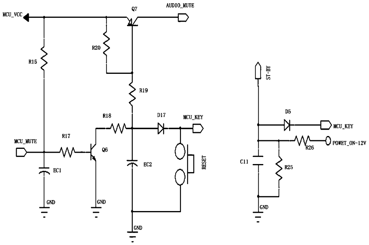
[0022] Such as figure 1 A circuit for synchronously controlling the mute function of a reset switch includes the following components: a first electrolytic capacitor EC1, a first resistor R15, a second resistor R17, a first triode Q6, a third resistor R18, a second electrolytic Capacitor EC2, fourth resistor R19, first diode D17, fifth resistor R20, second triode Q7, reset button RESET, second diode D5, capacitor C11, sixth resistor R25, seventh resistor R26 . The terminals connected with the mute circuit include: mute control terminal AUDIO_MUTE, MCU key MCU_KEY, MCU power supply terminal MCU_VCC, MCU mute terminal MCU_MUTE, power amplifier standby ST-BY.
[0023] The first transistor Q6 is an NPN transistor, and the second transistor Q7 is a PNP transistor.
[0024] The negative electrode of the first electrolytic capacitor EC1 is grounded, the positive electrode is respectively connected to the first resistor R15 , the second resistor R17 and the MCU mute terminal MCU_MUT...
Embodiment 2
[0027] On the basis of Embodiment 1, this embodiment adds a delay circuit, and the delay circuit includes a resistor and a capacitor. One end of the capacitor of the delay circuit is grounded, the other end is connected to the resistor, and one end of the resistor is connected to the delay circuit. The capacitors of the circuit are connected and provided with a first circuit inlet, and the other end is a second circuit inlet. The delay circuit is connected in parallel with the first diode D17.
[0028] The reset switch in Embodiment 1 can be replaced by a switch control circuit, which includes a circuit input terminal, a circuit output terminal, a third diode, a fourth diode, a third electrolytic capacitor, a ninth resistor and a tenth resistor . One end of the ninth resistor is grounded, the other end is connected to the cathode of the third diode and the circuit input terminal, the anode of the third diode is connected to the tenth resistor and the cathode of the fourth dio...
Embodiment 3
[0030] In this embodiment, on the basis of Embodiment 1, a vibrating circuit is added, and the vibrating circuit includes a circuit output terminal, a circuit access terminal, an eighth resistor, a third triode and a miniature vibrator. One end of the eighth resistor is connected to the output end of the circuit, the other end is connected to the base electrode of the third triode, the collector of the third triode is connected to the micro vibrator, the emitter of the third triode is grounded, and the micro vibrator The other end is connected to the circuit access end. As for the mechanical part, the miniature vibrator is installed inside the reset button.
[0031]The vibration circuit is connected in parallel with the circuit composed of the fourth resistor R19, the first diode D17 and the second triode through the circuit output terminal and the circuit access terminal. The purpose of the vibration circuit setting is that when the reset button is pressed, the instantaneous...
PUM
 Abstract
Description
Claims
Application Information
 - R&D
- Intellectual Property
- Life Sciences
- Materials
- Tech Scout
- Unparalleled Data Quality
- Higher Quality Content
- 60% Fewer Hallucinations
Browse by: Latest US Patents, China's latest patents, Technical Efficacy Thesaurus, Application Domain, Technology Topic, Popular Technical Reports.
© 2025 PatSnap. All rights reserved.Legal|Privacy policy|Modern Slavery Act Transparency Statement|Sitemap|About US| Contact US: help@patsnap.com