A compressed gas load switch for high-voltage gas-insulated ring main unit

A high-voltage gas and load switch technology, applied in high-voltage/high-current switches, high-voltage air circuit breakers, electric switches, etc., can solve problems such as uneven distribution of electric field, difficulty in ensuring concentricity of moving contacts, and complicated assembly process, etc., to achieve Improve reliability and stability, good reliable insulation, good effect of electric field uniformity

Active Publication Date: 2018-11-06
CEEPOWER (FUQING) CO LTD
View PDF5 Cites 0 Cited by
  • Summary
  • Abstract
  • Description
  • Claims
  • Application Information

AI Technical Summary

Problems solved by technology

[0002] The existing load switch has two structures: one is a knife-gate structure; the other is a three-phase integrated compressed air structure, which is bulky and heavy, with uneven electric field distribution and unstable insulation performance.
The former cools and extinguishes the arc through the arc extinguishing grid during the opening and closing process of the switch, and the arc extinguishing ability is not ideal. Although the arc extinguishing ability of the latter is ideal, the assembly process is complicated. The concentric rate of the process is difficult to guarantee, which causes the load switch to fail during the commissioning process
In addition, due to the existing three-phase integrated load switch, and as the switchgear becomes more and more miniaturized, the development trend of the switchgear has been limited.

Method used


Image

  • A compressed gas load switch for high-voltage gas-insulated ring main unit
  • A compressed gas load switch for high-voltage gas-insulated ring main unit
  • A compressed gas load switch for high-voltage gas-insulated ring main unit

Examples


Embodiment Construction

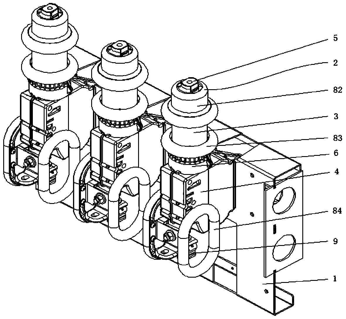
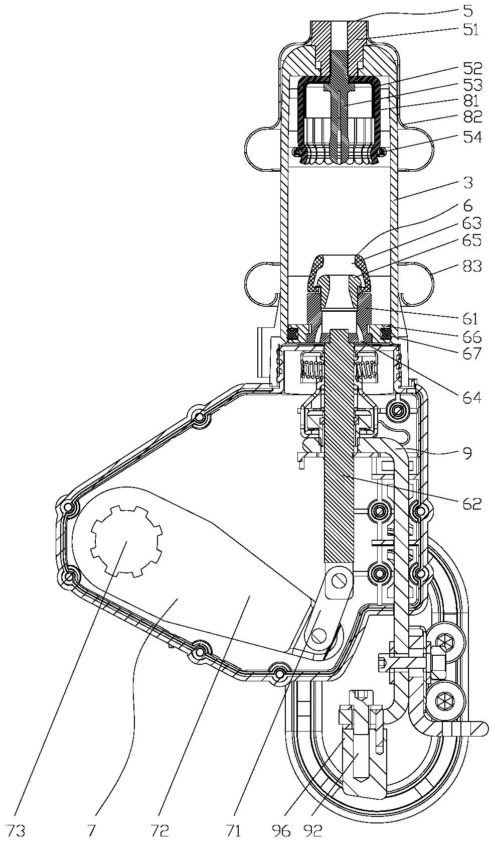
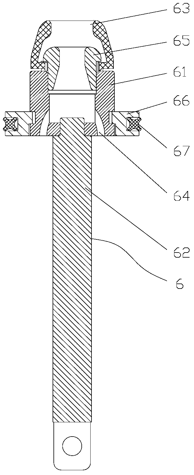
[0020] Such as Figure 1-6 As shown in one, the present invention includes a bracket 1, on which three switch units 2 are arranged, and the three switch units 2 form a three-phase integrated structure with the bracket 1, and the switch unit 2 includes an insulating cylinder 3, an insulating contact box 4. The static contact assembly 5, the moving contact assembly 6 and the crank arm assembly 7, the static contact assembly 5 and the moving contact assembly 6 are respectively arranged on the upper end and the lower end of the insulating cylinder 3, and the moving contact assembly 6 and the inner wall of the insulating cylinder 3 Contact to form an arc extinguishing chamber, the static contact assembly 5 includes a static contact seat 51 and a plum blossom static contact 52 arranged on the upper end of the insulating cylinder 3, and a plum blossom static contact 52 is provided with a pressure equalizing sleeve 81 and an arc strike needle 53 , one end of the arc striking needle 53...


PUM


Abstract

The invention relates to a pressure-operated load switch for a high-voltage gas insulation ring-network cabinet. The pressure-operated load switch comprises a bracket, wherein the bracket is provided with a plurality of independent switch units; each switch unit comprises an insulating cylinder, an insulating contact box, a fixed contact component, a moving contact component and a crank component; the fixed contact component and the moving contact component are arranged at the upper end and the lower end of the insulating cylinder; the moving contact component is in contact with the inner wall of the insulating cylinder to form an arc extinguish chamber; the fixed contact component comprises a fixed contact block and a tulip fixed contact; the fixed contact block is arranged at the upper end of the insulating cylinder; a pressure equalizing sleeve and a striking needle are arranged in the tulip fixed contact; one end of the striking needle and the fixed contact block are in threaded connection to fix the tulip fixed contact at the upper end of the insulating cylinder; the lower end of the insulating cylinder and the insulating contact box are in threaded connection; a uniform cover and a uniform ring are arranged at the periphery of the insulating cylinder corresponding to the fixed contact component and the moving contact component respectively; pressure equalizing rings are arranged at two sides out of the insulating contact box; the moving contact component comprises a moving contact and a moving contact rod; and the upper end of the moving contact rod and the lower end of the moving contact are in threaded connection.

Description

technical field [0001] The invention relates to the technical field of load switches, in particular to a compressed gas type load switch used in a high-voltage gas-insulated ring network cabinet. Background technique [0002] The existing load switch has two structures: one is a knife-gate structure; the other is a three-phase integrated compressed air structure, which is bulky and heavy, with uneven electric field distribution and unstable insulation performance. The former cools and extinguishes the arc through the arc extinguishing grid during the opening and closing process of the switch, and the arc extinguishing ability is not ideal. Although the arc extinguishing ability of the latter is ideal, the assembly process is complicated. The concentric rate of the process is difficult to guarantee, which causes the load switch to fail during the commissioning process. In addition, due to the existing three-phase integrated load switch, as the switchgear becomes smaller and ...

Claims


Application Information

Patent Timeline
Patent Type & Authority Patents(China)
IPC IPC(8): H01H33/22H01H33/52H01H33/70
CPCH01H33/22H01H33/52H01H33/7046
Inventor 余养乐周强陈友强
Owner CEEPOWER (FUQING) CO LTD
Why Eureka
Try Eureka