Drive mechanism and injection device herewith

A driving mechanism and injection device technology, which is applied in the field of pen-type drug delivery devices and injection devices, can solve problems such as user confusion, and achieve the effect of avoiding accidents

Active Publication Date: 2016-04-13
SANOFI SA
View PDF8 Cites 3 Cited by
  • Summary
  • Abstract
  • Description
  • Claims
  • Application Information

AI Technical Summary

Problems solved by technology

Thus, even if the user does not initiate the dispensing process, the user may be ...

Method used


Image

  • Drive mechanism and injection device herewith
  • Drive mechanism and injection device herewith
  • Drive mechanism and injection device herewith

Examples


Embodiment Construction

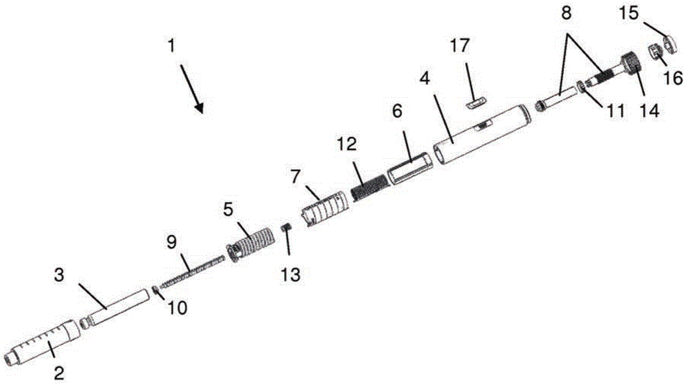
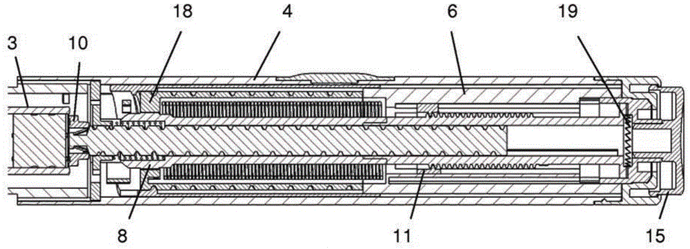
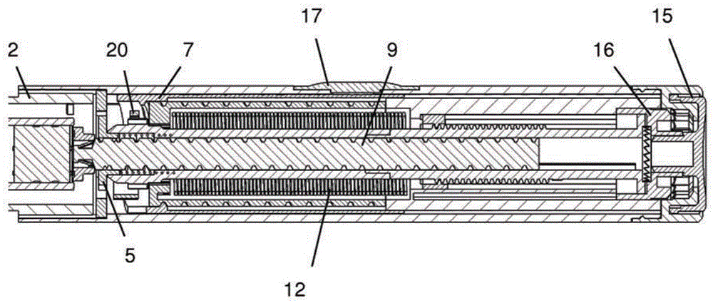
[0128] The injection device 1 according to the invention is figure 1 shown in an exploded view. The injection device 1 comprises a cartridge holder 2, a cartridge 3 and a drive mechanism. The drive mechanism includes an outer housing 4, an inner housing 5, a dose dial sleeve as a dial member 6, a digital sleeve as a display member 7, a drive sleeve as a drive member assembly 8, a lead screw 9, a bearing 10, Nut 11 , drive spring 12 , return spring 13 , dial handle 14 , dose button 15 and clutch plate 16 . All components are concentrically located about a common main axis of the mechanism. In more detail, the drive member assembly 8 surrounds the lead screw 9, the torsion spring 12 surrounds the drive member 8, the dial member 6 and inner housing 4 surround the torsion spring 12, the display member 7 surrounds the dial member 6, and the outer housing 4 surrounds the display Component 7. Furthermore, the nut 11 and the clutch plate 16 are located between the drive member ass...


PUM


Abstract

The present invention relates to a drive mechanism which is suitable for an injection device (1; 101; 201; 301; 401), especially a pen type drug delivery device. The mechanism comprises a housing (4; 104; 204; 304; 404), a dosing member (7; 107; 206; 306; 407), which during dose setting, dose resetting and dose dispensing rotates relative to the housing between a zero dose position and a maximum dose position, and an insert (5; 126; 205; 307; 431) which is rotationally constrained to the housing. The dosing member (7; 107; 206; 306; 407) and the insert (5; 126; 205; 307; 431) each comprise at least one abutment feature (22, 24; 122, 24; 222; 422, 424) contacting each other when the dosing member (7; 107; 206; 306; 407) reaches its zero dose position during dose dispensing, wherein an audible and/or tactile feedback is generated by the contact of the abutment features (22, 24; 122, 124; 222; 422, 424).

Description

technical field [0001] The present invention relates to a drive mechanism suitable for use in injection devices, especially pen-type drug delivery devices. The mechanism comprises a housing and a dosing member which rotates relative to the housing between a zero dose position and a maximum dose position during dose setting, dose resetting and dose dispensing. Furthermore, the invention relates to an injection device comprising such a drive mechanism and a cartridge containing a medicament. Background technique [0002] Hereinafter, the distal end of the injection device or the drive mechanism refers to the end where the cartridge and eg the needle are located, while the opposite end is the proximal end. A dose button may be provided at the proximal end. [0003] The general function of the drive mechanism defined above is to set a dose and subsequently dispense the set dose. Dose setting (dose dial) typically requires the user to manipulate an element of the drive mechani...

Claims


Application Information

Patent Timeline
IPC IPC(8): A61M5/20A61M5/315
CPCA61M5/20A61M5/31535A61M5/31541A61M5/31553A61M5/3157A61M5/31578A61M5/31583A61M2205/581A61M2205/582
Inventor D·A·普伦特里S·L·比尔顿
Owner SANOFI SA
Why Eureka
Try Eureka