
Reciprocating saw mechanism

A technology of reciprocating saws and reciprocating rods, which is applied in the field of reciprocating saws and can solve problems such as faults and power reduction of reciprocating saws

Inactive Publication Date: 2016-04-13
HILTI AG
View PDF7 Cites 0 Cited by
  • Summary
  • Abstract
  • Description
  • Claims
  • Application Information

AI Technical Summary

Problems solved by technology

The function of bearings, seals and other critical components can eventually be adversely affected in part by dust deposits, which can lead to reduced power or even complete failure of the reciprocating saw

Method used


Image

  • Reciprocating saw mechanism
  • Reciprocating saw mechanism
  • Reciprocating saw mechanism

Examples


Embodiment Construction

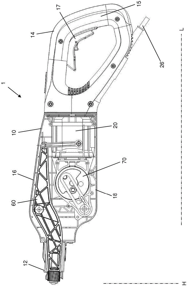
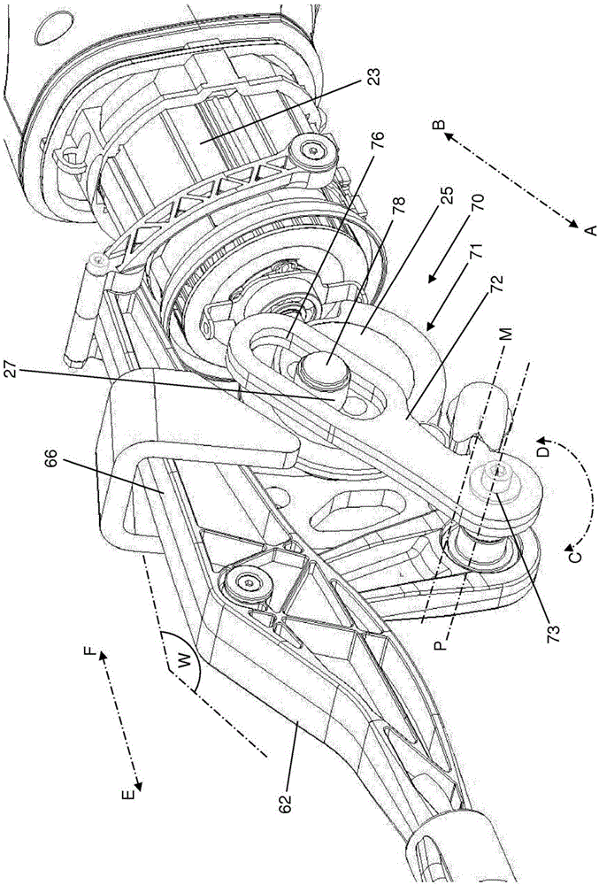
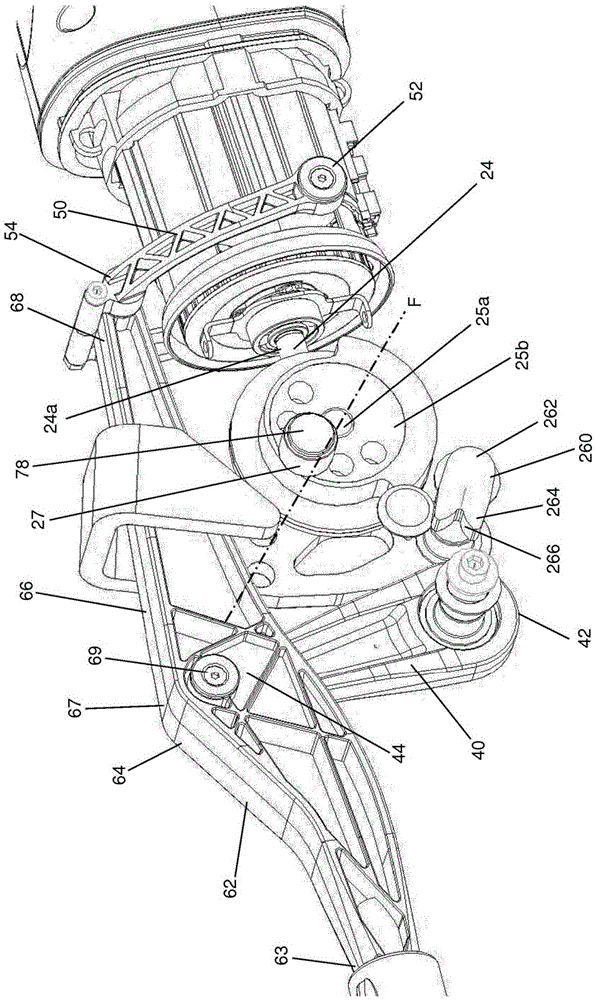
[0037] Figures 1 to 10 A first embodiment of a reciprocating saw 1 according to the invention is shown, which basically comprises a reciprocating saw housing 10, a drive 20, a first articulation rod 40, a second articulation rod 50, a reciprocating rod 60, a connecting device 70, A saw, not shown, and a control, not shown.

[0038] The reciprocating saw housing 10 has a first housing end 12 , a second housing end 14 , a housing top side 16 and a housing bottom side 18 . The saw is positioned on a first housing end 12 and has a handle 15 with a switch member 17 on a second housing end 14 . The drive 20 , the first articulated rod 40 , the second articulated rod 50 , the reciprocating rod 60 and the control are at least partially housed in the reciprocating saw housing 10 .

[0039] The driver 20 includes a driver housing 22 , an electric motor 23 including a drive shaft 24 and a drive wheel 25 , and an energy supply 26 . The electric motor 23 can be a DC motor or an AC moto...


PUM


Abstract

Reciprocating saw (1) for machining a workpiece, in particular a mineral or metallic workpiece, comprising a drive (20) and a stroke rod (60) having a first stroke rod end (63), a second stroke rod end (68) and a drive point (69). Furthermore, a first articulated rod (40) having a pivot point (42) and a connecting point (44) and a second articulated rod (50) having a first pivot point (52) and a second pivot point (54) are provided, wherein the pivot point (42) of the first articulated rod (40) can be rotatably connected to the drive point (69) of the stroke rod (60), and the connecting point (44) of the first articulated rod (40) can be connected to the drive (20) for conjoint rotation therewith by means of a connecting device (70), and wherein the drive (20) can be positioned at least partially in a drive housing.

Description

technical field [0001] The invention relates to a reciprocating saw for machining workpieces, in particular mineral or metallic materials ( ). The reciprocating saw includes a driver and a reciprocating rod having a first reciprocating rod end, a second reciprocating rod end, and a drive point. Background technique [0002] Reciprocating saws of the aforementioned type are basically known and are mainly provided in machines for sanitary, heating and climate technology, carpentry and building carpentry applications. Reciprocating saws are also known as reciprocating saws, lift saws, or tiger saws. The most common applications of such saws are demolition of old structural members and separation of pipes, conduits or the like. There are specific guides for separating the metal tubes which facilitate straight cuts. Different materials can be processed according to the choice and characteristics of the saw blade. Saw blade options are used for metal, wood, plastic, blank cu...

Claims


Application Information

Patent Timeline
Patent Type & Authority Applications(China)
IPC IPC(8): B23D51/16
CPCB23D51/16
Inventor G·哈斯
Owner HILTI AG
Learn More