Composite molded product and method for manufacturing same

A manufacturing method and composite molding technology, which can be applied to layered products, other household appliances, conductive adhesive connections, etc., can solve the problems of time-consuming, difficult to volatilize solvents, dissolution of base film or abnormal swelling and appearance, etc. effect of the problem

Active Publication Date: 2016-04-13
NISSHA PRINTING COMPANY
View PDF6 Cites 11 Cited by
  • Summary
  • Abstract
  • Description
  • Claims
  • Application Information

AI Technical Summary

Problems solved by technology

At this time, since the contact pin is inserted after the conductive adhesive is injected into the bottom of the insertion hole in contact with the electrode circuit layer, it is easy to cause the following problems: the solvent in the conductive adhesive is difficult to volatilize, and the adhesive It takes time until the mixture is dried and set, and the basement membrane dissolves or swells due to the action of the solvent, causing abnormalities in appearance

Method used


Image

  • Composite molded product and method for manufacturing same
  • Composite molded product and method for manufacturing same
  • Composite molded product and method for manufacturing same

Examples


no. 1 approach

[0070] Below, use figure 1 and even Figure 7 The composite molded product and its manufacturing method according to the first embodiment of the present invention will be described.

[0071] (1) Overview of composite molded products

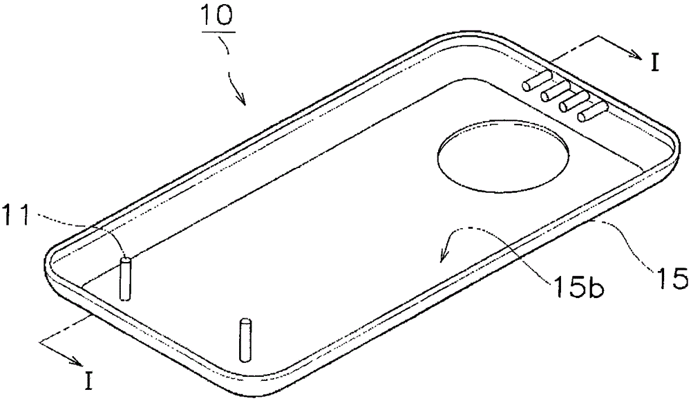
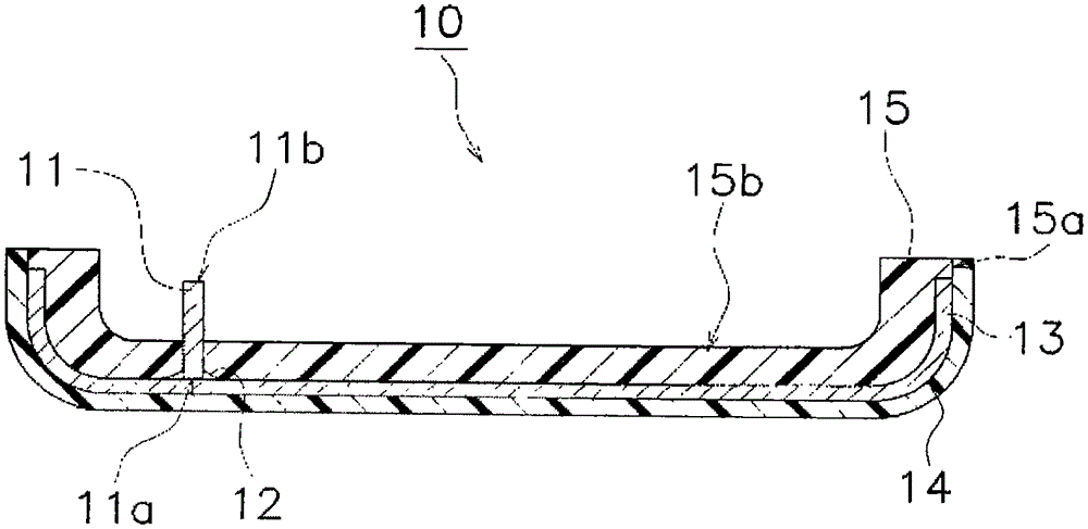
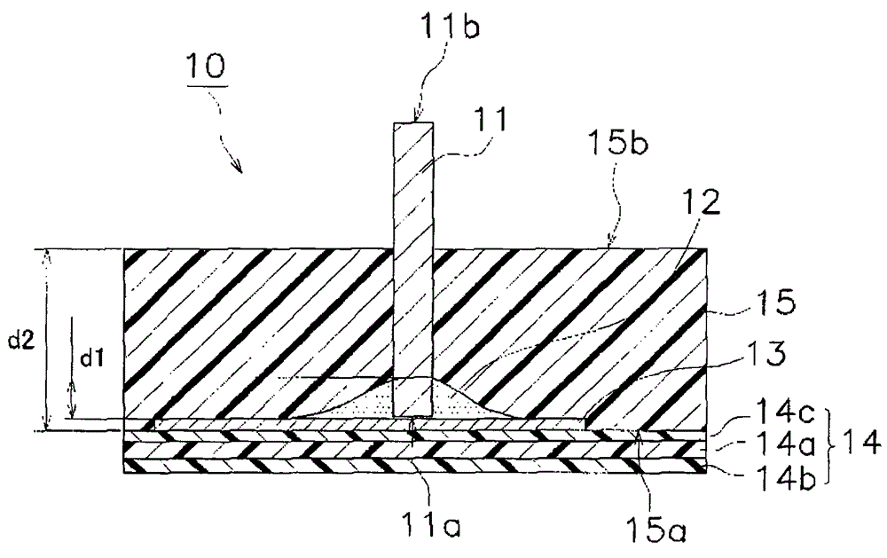
[0072] figure 1 It is a perspective view for explaining the outline of the structure of the composite molded article which concerns on 1st Embodiment of this invention. figure 2 for along figure 1 Cross-sectional view of the I-I line. In addition, in image 3 in, zoomed in on figure 2 The periphery of the connection portion of the contact pin and the electrode pattern layer in the cross-sectional configuration shown in .

[0073] figure 1 and even image 3 A composite molded product 10 shown in , includes a contact pin 11 , a conductive adhesive 12 , an electrode pattern layer 13 , a transfer layer 14 , and a molded body 15 . The molded body 15 has a structure obtained by molding a thermoplastic resin by injection molding described la...

no. 2 approach

[0103] (4) Overview of composite molded products

[0104] Next, use Figure 8 and even Figure 10 A composite molded article according to a second embodiment of the invention will be described. Figure 8 A composite molded product 10A according to the second embodiment is shown, Figure 9 (a) shows the contact pin 11F used for the composite molded product 10A. Figure 10 (a) means along Figure 8 The section of line II-II, Figure 10 (b) shows a section along line III-III. The composite molded product 10A according to the second embodiment differs from the composite molded product 10 according to the first embodiment in that the shape of the contact pin 11F is a flat plate extending in a strip shape; This point supports the protrusion 16 and the rib 17 . Since the composite molded product 10A according to the second embodiment has the same basic structure as the composite molded product 10 according to the first embodiment, the composite molded product 10A will be descr...

no. 3 approach

[0118] (6) Overview of composite molded products

[0119] In the composite molded articles 10 and 10A according to the first and second embodiments described above, the contact pins 11 and 11F are exposed on the side opposite to the electrode pattern layer 13 and the transfer layer 14 . However, the direction in which the contact pins are exposed may be the opposite side to the composite molded product 10, 10A. For example, the electrode pattern layer 13 may have a structure through which contact pins penetrate.

[0120] Figure 11 The composite molded product 10B according to the third embodiment shown has a structure in which contact pins 11F penetrate through the electrode pattern layer 13 . Figure 11 The contact pin 11F shown is used as Figure 10 (a) As already described, the opening 11Fc is formed in the one end 11Fa and the other end 11Fb.

[0121] The other end 11Fb of the contact pin 11F penetrates not only the electrode pattern layer 13 but also the conductive a...


PUM

PropertyMeasurementUnit
thicknessaaaaaaaaaa
thicknessaaaaaaaaaa
thicknessaaaaaaaaaa

Abstract

The problem to be solved by the invention of the present application is to suppress a malfunction caused by embedding a contact pin in a molded body, and reliably electrically connect the contact pin and an electrode pattern layer. The invention of the present application is a composite molded product (10) provided with: an insulating molded body (15) which is formed by being molded into a predetermined shape; an insulating transfer layer (14) which covers at least part of the surface of the molded body (15); an electrode pattern layer (13) which is formed between the molded body (15) and the transfer layer (14); a conductive contact pin (11) one end side of which is buried and secured in the molded body (15) and the other end of which is exposed from the molded body; and a conductive adhesive (12) which is formed between the electrode pattern layer (13) and the molded body (15) and adheres to the electrode pattern layer (13) and the contact pin (11) to form the electric connection between the electrode pattern layer (13) and the contact pin (11).

Description

technical field [0001] The present invention relates to a composite molded product in which a contact pin is embedded in a molded body and a method for manufacturing the same. Background technique [0002] Conventionally, as a method of electrically connecting contact pins and electrode patterns, a connection method based on outsert molding is known. The existing connection method based on injection molding on a substrate is a method in which, for example, as described in Patent Document 1, an insertion hole reaching the electrode pattern is formed when the electrode pattern on the base film is covered with a molding resin, and through After the conductive adhesive is injected into the insertion hole, the contact pin is inserted to electrically connect the contact pin to the electrode pattern. [0003] prior art literature [0004] patent documents [0005] Patent Document 1: Japanese Patent Laid-Open No. 2013-80632 Contents of the invention [0006] In the existing me...

Claims


Application Information

Patent Timeline
Patent Type & Authority Applications(China)
IPC IPC(8): B32B7/02B29C45/14H01R4/04H01R12/59
CPCH01R43/24B29L2031/3437B29C45/14065B29C45/1418B29C45/14426B29C45/14639B29C45/14016B32B7/12B32B2307/202B32B2457/00H01R4/04B29C2045/14147B29K2101/12
Inventor 山崎成一东川季裕
Owner NISSHA PRINTING COMPANY
Why Eureka
Try Eureka