Novel liquid spot-spray torch and spot-spray method thereof

A liquid and new technology, applied in the direction of liquid injection device, injection device, etc., can solve the problems of low injection frequency, easy clogging of nozzles, difficult cleaning, etc., and achieve the effects of high control accuracy, improved production efficiency, and fast dynamic response.

Active Publication Date: 2016-04-20
广州高印力信息技术有限公司
View PDF6 Cites 9 Cited by
  • Summary
  • Abstract
  • Description
  • Claims
  • Application Information

AI Technical Summary

Problems solved by technology

[0002] Liquid spray gun is an indispensable device in many automation equipment. It is widely used in food and drug packaging, automatic spraying, automatic cleaning, electronic circuit board, liquid crystal display and other fields. Among the existing traditional spray guns, the spraying principle is mostly, compressed air After filtering and regulating pressure and controlling the electromagnetic valve, it enters the spray gun. The solution to be sprayed enters the spray gun through pressure or siphon. The excitation coil and spring control the switch of the valve needle to control the spraying and stopping of the liquid. The amount of liquid sprayed each time can be used for your country The fine-tuning knob is used to adjust, but the spraying frequency of this traditional spray gun is relatively low (generally no more than 500 times / minute), and it is difficult to meet the spraying requirements of high precision, high frequency, and high flexibility. At the same time, when spraying high-viscosity solutions (such as Glue spraying), because the valve needle is in contact with liquid and gas, the nozzle is easy to block and cleaning is difficult

Method used


Image

  • Novel liquid spot-spray torch and spot-spray method thereof
  • Novel liquid spot-spray torch and spot-spray method thereof

Examples


Embodiment Construction

[0017] The present invention will be described in further detail below in conjunction with the accompanying drawings.

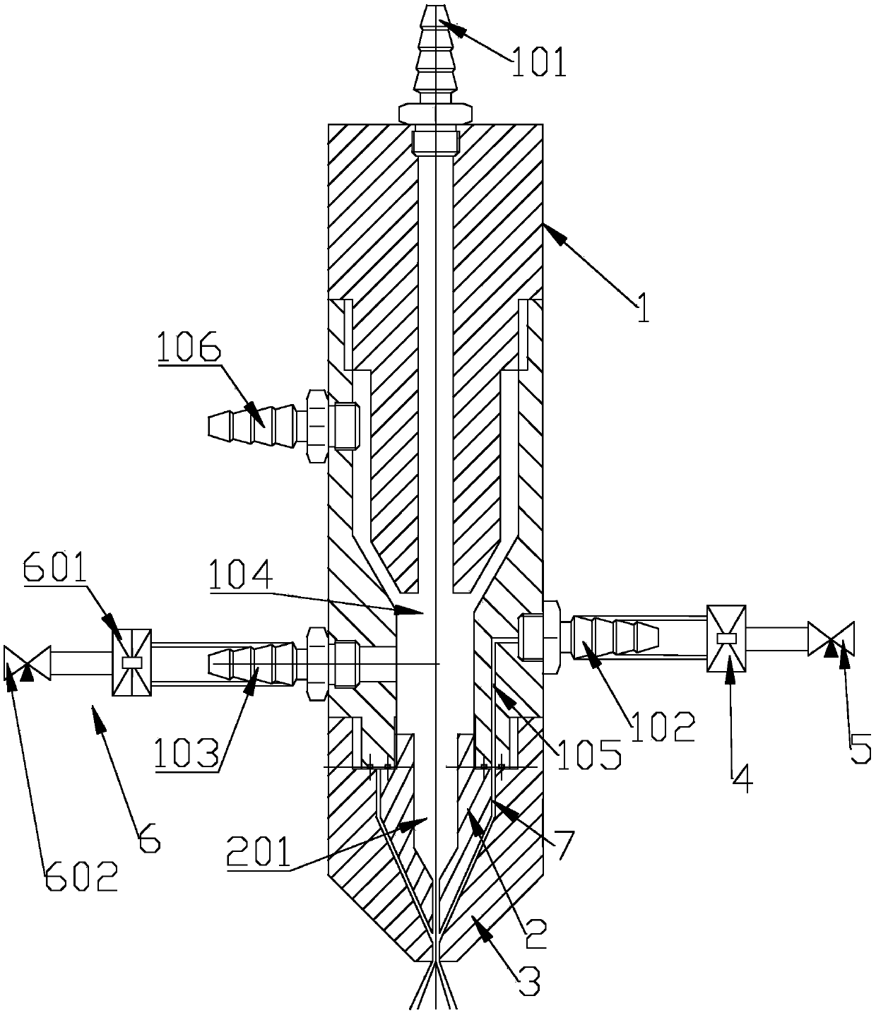
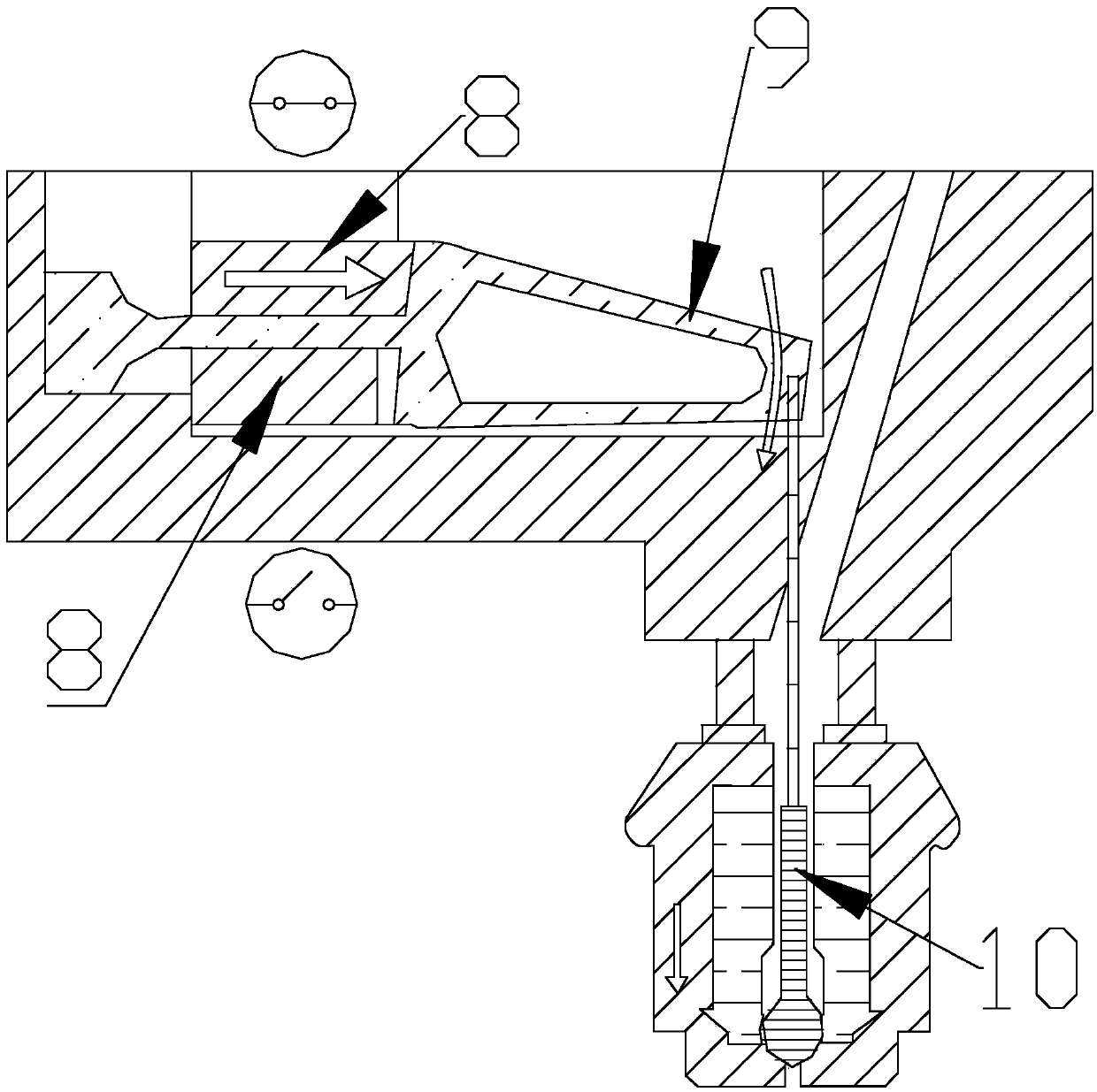
[0018] Figure 1 ~ Figure 2 A novel liquid spot spray gun according to one embodiment of the present invention is schematically shown. Such as figure 1 As shown, the new liquid point spray gun includes a spray gun body 1, an air guide cone 2 and a nozzle 3. The spray gun body 1 is provided with a liquid inlet 101, an air inlet 102, and a negative pressure port 103. The inside of the spray gun body 1 is provided with a first A liquid storage chamber 104, a first air chamber 105, the liquid inlet 101 communicates with the first liquid storage chamber 104, one end of the air inlet 102 communicates with the first air chamber 105, and the other end of the air inlet 102 communicates with the piezoelectric ceramic direct drive The valve 4 is connected, the piezoelectric ceramic direct drive valve 4 is connected with the first pressure regulating valve 5, the negat...


PUM


Abstract

The invention discloses a novel liquid spot-spray torch and a spot-spray method thereof, comprising a torch body, an air guide cone and a nozzle. The torch body is provided with a liquid inlet, an air inlet and a negative pressure port, the torch body is internally provided with a first liquid storage cavity and a first air cavity, the liquid inlet is communicated with the first liquid storage cavity, one end of the air inlet is communicated with the first air cavity, the other end of the air inlet is connected with a piezoceramic direct-drive valve which is connected with a first pressure adjusting valve, the negative pressure port is close to a liquid incoming end of the torch body, one end of the negative pressure port is communicated with the first liquid storage cavity, the other end of the negative pressure port is connected with a negative pressure generator, the air guide cone is connected with a liquid outgoing end of the torch body, the air guide cone is internally provided with a second liquid storage cavity which is communicated with the first liquid storage cavity, the nozzle sleeves the liquid outgoing end of the torch body, and the inner wall of the nozzle and the outer wall of the air guide cone form a second air cavity which is communicated with the first air cavity. The novel liquid spot-spray torch and the spot-spray method thereof have the advantages that the spraying requirements for high frequency and high precision can be met, high-speed spot spraying can be implemented, and production efficiency can be improved.

Description

technical field [0001] The invention relates to the field of liquid spraying, in particular to a novel liquid point spraying spray gun and a point spraying method thereof. Background technique [0002] Liquid spray gun is an indispensable device in many automation equipment. It is widely used in food and drug packaging, automatic spraying, automatic cleaning, electronic circuit board, liquid crystal display and other fields. Among the existing traditional spray guns, the spraying principle is mostly, compressed air After filtering and regulating pressure and controlling the electromagnetic valve, it enters the spray gun. The solution to be sprayed enters the spray gun through pressure or siphon. The excitation coil and spring control the switch of the valve needle to control the spraying and stopping of the liquid. The amount of liquid sprayed each time can be used for your country The fine-tuning knob is used to adjust, but the spraying frequency of this traditional spray g...

Claims


Application Information

Patent Timeline
Patent Type & Authority Applications(China)
IPC IPC(8): B05B7/04B05B7/12
CPCB05B7/0483B05B7/12
Inventor 刘小栋梁中华王学理屈晔南王鹏武吉梅梁同同张赛
Owner 广州高印力信息技术有限公司
Why Eureka
Try Eureka