Rotor type mixing component

A technology of mixing and components, which is applied in the field of new rotors, can solve the problems of poor adaptability, poor material adaptability, and affecting the promotion and use of equipment, and achieve the effects of favorable homogenization, promoting backflow, and slowing down shearing

Inactive Publication Date: 2016-04-20
JILIN DESIGNING INST OF CNPC NORTHEAST REFINING & CHEM ENG
View PDF4 Cites 5 Cited by
  • Summary
  • Abstract
  • Description
  • Claims
  • Application Information

AI Technical Summary

Problems solved by technology

[0006] The rotor-type mixing element involved in the present invention solves the poor adaptability to materials in the prior art, especially the poor adaptability to materials with high and low melt indices and poor adaptability to output fluctuations. Problems affecting the promotion and use of this type of equipment

Method used


Image

  • Rotor type mixing component
  • Rotor type mixing component
  • Rotor type mixing component

Examples


Embodiment Construction

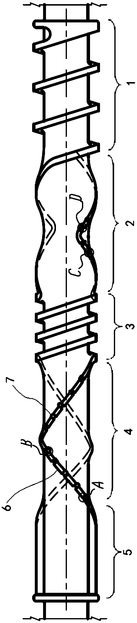
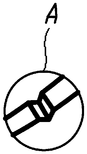
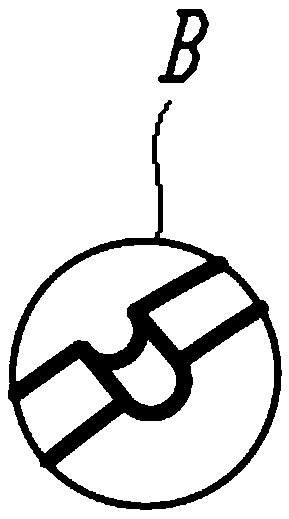
[0024] In one embodiment of the rotor-type mixing element of the present invention, such as figure 1 As shown, the rotor-type mixing element of this embodiment includes a feed section 1, a first mixing section 2, a conveying section 3, a second mixing section 4 and a discharge section 5, and the mixing section 2 is provided with at least two pairs of screw rib 6, and the top of the screw rib 6 is provided with a groove 7.

[0025] The processing capacity of the double rotor continuous mixer is directly proportional to the size of the free volume in the barrel. The shape of the rotor end face of the current continuous mixer is usually oval. The material is subjected to a large shearing action at the top of the screw flight 6, and the particle agglomerates are crushed and dispersed. However, when the material is subject to a large shearing action at the top of the screw flight 6, it will cause the degradation of the polymer melt. Slotted 7 rotors, such as figure 1 shown.

...


PUM

PropertyMeasurementUnit
breaking strengthaaaaaaaaaa
elongation at breakaaaaaaaaaa

Abstract

The invention relates to a rotor type mixing component. The rotor type mixing component comprises a feeding section, a first mixing section, a conveying section, a second mixing section and a discharging section which are sequentially arranged in the feeding direction. The first mixing section and the second mixing section are each provided with a plurality of pairs of screw flights. The top of each pair of screw flights is provided with a groove. Accordingly, the rotor type mixing component can relieve the shearing effect borne by the tops of the screw flights, backflow of some mixed materials is facilitated, original flowing of a rotor boosting face is disturbed, and homogenization of the material components is facilitated.

Description

technical field [0001] The invention relates to the technical field of high polymer processing machinery, in particular to a novel rotor used in a double-rotor continuous mixer. Background technique [0002] Double-rotor continuous mixing machine is a new type of continuous mixing machine developed and manufactured by the American Farrel Company in the mid-1960s on the basis of its famous brand product Banbury internal mixer. The shape of the machine is similar to a twin-screw extruder, but the feeding and discharging methods are different. The machine is mainly composed of barrel, rotor, unloading device and other parts. The mixing chamber on the barrel is two interconnected holes with an ∞ cross-section. The mixing section of the rotor is more like a pair of internal mixer rotors, and the discharge device is composed of a discharge door and an adjustment device. The material is sheared, pulverized, kneaded and mixed by the rotor in the mixing chamber. By adjusting the ...

Claims


Application Information

Patent Timeline
Patent Type & Authority Applications(China)
IPC IPC(8): B29B7/42
CPCB29B7/42B29B7/429
Inventor 李欣平石文彪周江沛缪国斌潘磊周小伟史舸
Owner JILIN DESIGNING INST OF CNPC NORTHEAST REFINING & CHEM ENG
Why Eureka
Try Eureka