
Sponge foaming machine

A technology of foaming machine and sponge, which is applied in the field of sponge foaming machine, can solve problems such as raw material overflow, and achieve the effects of accurate flow rate, compact use of space, and sufficient mixing of raw materials

Inactive Publication Date: 2016-04-20
DONGGUAN ZHENFENG MACHINERY MFG CO LTD
View PDF0 Cites 1 Cited by
  • Summary
  • Abstract
  • Description
  • Claims
  • Application Information

AI Technical Summary

Problems solved by technology

[0005] The current mixing box is a sealed chamber, and the traditional feeding method adopts normal pressure pouring. During the foaming process of the mixing box, it is easy to generate positive pressure in the mixing box, causing the raw materials to overflow from the feeding pipe.

Method used


Image

  • Sponge foaming machine
  • Sponge foaming machine
  • Sponge foaming machine

Examples


Embodiment Construction

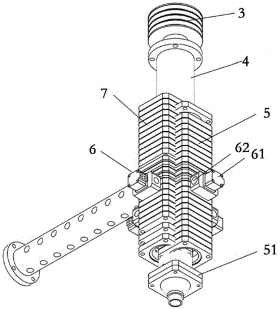
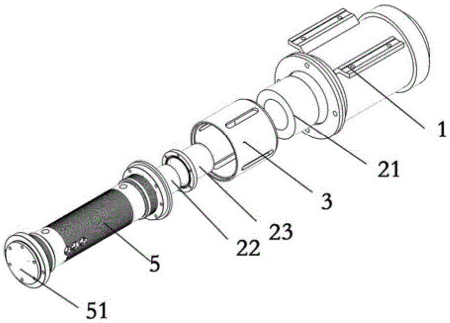
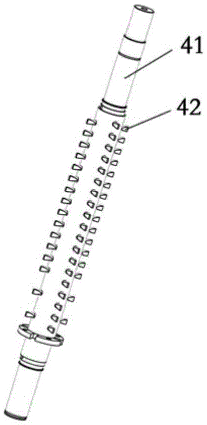
[0027] see Figure 1-3 As shown, the present invention relates to a sponge foaming machine, including a motor 1, a main mixing box 7, an auxiliary mixing box 5, a sealing connector 2, a sealing sleeve 3 and a stirring rod 4, and the auxiliary mixing box 5 is located in the main mixing box One side of the 7 side is connected with the main mixing box, the main mixing box 7 is a box body with a bottom wall and a side wall integrally formed with an opening, and the bottom wall of the auxiliary mixing box 5 is fixedly connected with a raised support seat 51, and the support seat 51 is It is cylindrical and has a circular slot on the upper end surface. The lower end of the stirring rod 4 is embedded in the circular slot of the support seat 51. The sealing connector 2 is arranged in the sealing sleeve 3. The sealing connector 2 The outer magnet 21 and the inner magnet 22 with a cover are nested sequentially from top to bottom. In order to increase the adsorption force between the out...


PUM

PropertyMeasurementUnit
angleaaaaaaaaaa

Abstract

The invention relates to the production technical field of sponges applied to furniture, bust, shoe materials, electronics, packaging, clothing industry, cars, aviation and the like, in particular to a sponge foaming machine. The sponge foaming machine comprises a motor, a primary mixing box, an auxiliary mixing box, a sealing connector, a sealing sleeve and a stirring rod, wherein the auxiliary mixing box is arranged at one side of the primary mixing box, and is communicated with the primary mixing box; the primary mixing box is a box body, wherein the box body is provided with a bottom wall and side walls which are integrally formed, and is provided with an opening; the sealing connector is arranged in the sealing sleeve; the output shaft of the motor is connected to the upper end of the sealing connector; the stirring rod is connected to the lower end of the sealing connector; the stirring rod is inserted into the auxiliary mixing box; a plurality of high-pressure spray nozzles are arranged on the side walls; the high-pressure spray nozzles are respectively connected to a compressed air power assembly and a feeding hole; the feeding hole is used for continuously feeding materials to the high-pressure spray nozzles through a pipeline; and the compressed air power assembly is used for providing power to the high-pressure spray nozzles through the pipeline.

Description

technical field [0001] The invention relates to the technical fields of sponge production applied to furniture, busts, shoe materials, electronics, packaging, clothing, automobiles, aviation, etc., especially a sponge foaming machine. Background technique [0002] Polyurethane soft foam rubber, polyurethane is the most common polymer material in life, widely used in the production of various "sponge" products. And elastic materials for shock absorption and anti-friction purposes, such as shoe soles, tractor tank track substrates. The foaming resin, foaming aid and binder resin (to make the finished product have adhesiveness) are mixed together, and the foaming process is carried out in the mixing chamber. The composition of the sponge is mostly polyurethane, just like foaming. The same material and different manufacturing processes will produce different things. PU sponge mainly includes polyester and polyether types. It can be sliced ​​or rolled, and can also be processed ...

Claims


Application Information

Patent Timeline
Patent Type & Authority Applications(China)
IPC IPC(8): B29C44/34C08G18/48
CPCB29C44/3442C08G18/48C08G2101/00
Inventor 潘诚
Owner DONGGUAN ZHENFENG MACHINERY MFG CO LTD
Learn More