
Multifunctional television rear shell mould

A TV and multi-functional technology, applied in the field of multi-functional TV rear shell molds, can solve the problems of lower raw material temperature, no heat dissipation holes, and many operating processes, so as to reduce operating tools, reduce operating processes, and save operating time Effect

Inactive Publication Date: 2016-04-20
TIANJIN LIANXINYING PLASTIC TECH
View PDF0 Cites 3 Cited by
  • Summary
  • Abstract
  • Description
  • Claims
  • Application Information

AI Technical Summary

Problems solved by technology

The back shell of the TV is an important part of the TV. Generally, the back shell is processed through a mold. The mold is divided into an injection mold and a stamping mold. The TV back shell is mostly made of an injection mold, but the mold formed by injection molding generally does not The heat dissipation hole requires post-processing to make the heat dissipation hole, and the operation process is many, time-consuming and laborious
The general injection mold is that the injection molding machine directly injects the raw materials into the mold, but sometimes due to the problems of the mold or the injection molding environment, the temperature of the injected raw materials is easy to drop, resulting in injection molding failure

Method used


Image

  • Multifunctional television rear shell mould
  • Multifunctional television rear shell mould

Examples


Embodiment 1

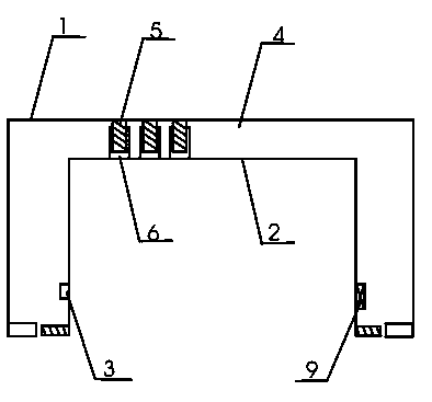
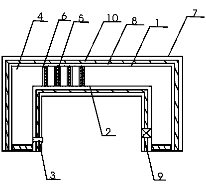
[0011] The present invention is a multi-functional television rear case mold, which includes an upper mold 1, a lower mold 2, a glue injection hole 3, and a molding cavity 4, and is characterized in that it also includes a heat dissipation protrusion 5, a heat dissipation concave hole 6, an insulation layer 7, Heating layer 8, exhaust hole 9, flowing water cooling layer 10, the upper mold 1 and the lower mold 2 are fastened together by a fixed structure to form a molding cavity 4, and the upper mold 1 is provided with a heat dissipation protrusion 5, and the heat dissipation protrusion 5 and the lower mold The heat dissipation concave holes 6 on the mold 2 are matched, and the upper mold 1 is sequentially provided with a heating layer 8, a flowing water cooling layer 10, and an insulating layer 7, and the lower mold 2 is also sequentially provided with a heating layer 8, a flowing water cooling layer 10, and an insulating layer. 7. One side of the lower mold 2 is provided with ...

Embodiment 2

[0013] When in use, first fasten the upper mold 1 and the lower mold 2 together, the heat dissipation protrusion 5 and the heat dissipation concave hole 6 are fixed together to achieve a good fixing effect, the raw material is injected into the molding cavity 4 through the injection hole 3, and the heating is turned on The heater in layer 8 heats the raw materials, and the insulation layer 7 keeps the raw materials warm. During injection molding, the gas in the molding cavity 4 is discharged out of the cavity through the exhaust hole 9, ensuring the quality of the product. When the injection molding is completed, stop the injection molding Then, cold water is injected into the flowing water cooling layer 10 through the water injection hole, and the cold water flows through the flowing water cooling layer 10 and then is discharged to the outside through the drainage hole.


PUM


Abstract

The invention provides a multifunctional television rear shell mould including: an upper mould, a lower mould, a glue injecting hole and a moulding chamber, and also including: heat dissipating projections, heat dissipating concave holes, a heat insulating layer, a heating layer, exhaust pores and a water-flow cooling layer. The upper mould and the lower mould are buckled to each other through a fixing structure to form the moulding chamber. The mould is provided with the heat dissipating projections and the heat dissipating concave holes so that heat dissipating holes and a television rear shell can be moulded successively, thereby reducing operation process and saving processing cost. The heat insulating layer, heating layer and water-flow cooling layer also have the heating, heat-insulating and temperature-reducing functions, so that the mould not only saves energy but also reduces operation tools, thereby simplifying operation steps and reducing operation times. When the heat dissipating projections and the heat dissipating concave holes are fixed together, a certain fixing effect is achieved, and meanwhile with the fastening structure of the upper mould and the lower mould, the upper mould and the lower mould can be fastened better, thereby ensuring tight fixation of the mould.

Description

technical field [0001] The invention relates to the field of television manufacturing, in particular to a mold for a multifunctional television rear shell. Background technique [0002] With the development of science and technology, people's living standards are gradually improved, and people's spare time is also gradually increasing, and television has become the main part of people's spare time. The back shell of the TV is an important part of the TV. Generally, the back shell is processed through a mold. The mold is divided into an injection mold and a stamping mold. The TV back shell is mostly made of an injection mold, but the mold formed by injection molding generally does not The heat dissipation hole requires post-processing to make the heat dissipation hole, and the operation process is many, time-consuming and laborious. In general injection molds, the injection molding machine directly injects raw materials into the mold, but sometimes due to problems with the m...

Claims


Application Information

Patent Timeline
IPC IPC(8): B29C45/26B29C45/73B29C45/34
Inventor 任富疆杜国辉
Owner TIANJIN LIANXINYING PLASTIC TECH
Features
  • Generate Ideas
  • Intellectual Property
  • Life Sciences
  • Materials
  • Tech Scout
  • Unparalleled Data Quality
  • Higher Quality Content
  • 60% Fewer Hallucinations
Learn More