
Brake pedal assembly

A technology of brake pedal and brake pedal arm, which is applied in the direction of foot-operated starting devices, etc., can solve the problems of the driver's less choice, affect the brake pedal feel, and affect the braking effect, so as to improve comfort and safety sexual effect

Inactive Publication Date: 2016-04-20
ANHUI JIANGHUAI AUTOMOBILE GRP CORP LTD
View PDF8 Cites 5 Cited by
  • Summary
  • Abstract
  • Description
  • Claims
  • Application Information

AI Technical Summary

Problems solved by technology

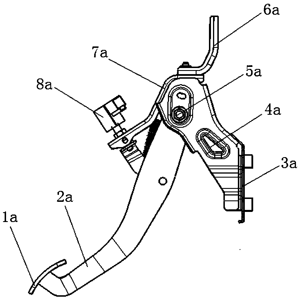
[0005] 1. Although the design of the brake pedal assembly, especially the brake pedal 1a, needs to be checked by ergonomics, the position and angle of the brake pedal 1a should be suitable for most drivers, but for some drivers , the brake pedal 1a is not in the most suitable position, and the height or angle of the brake pedal 1a cannot be adjusted. The driver needs to adapt to the position and angle of the brake pedal 1a, and may complain that the height of the brake pedal surface is too high , the angle of the brake pedal surface is unreasonable, etc., which will affect the feel of the brake pedal and even affect the braking effect
[0006] 2. Similarly, because the brake pedal 1a cannot be adjusted, the difference that the driver wants to pursue, such as widening the longitudinal or lateral width of the brake pedal surface, will basically not be realized, and the driver has less options

Method used


Image

  • Brake pedal assembly
  • Brake pedal assembly
  • Brake pedal assembly

Examples

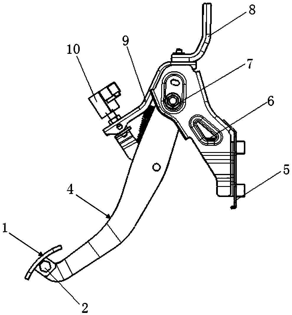
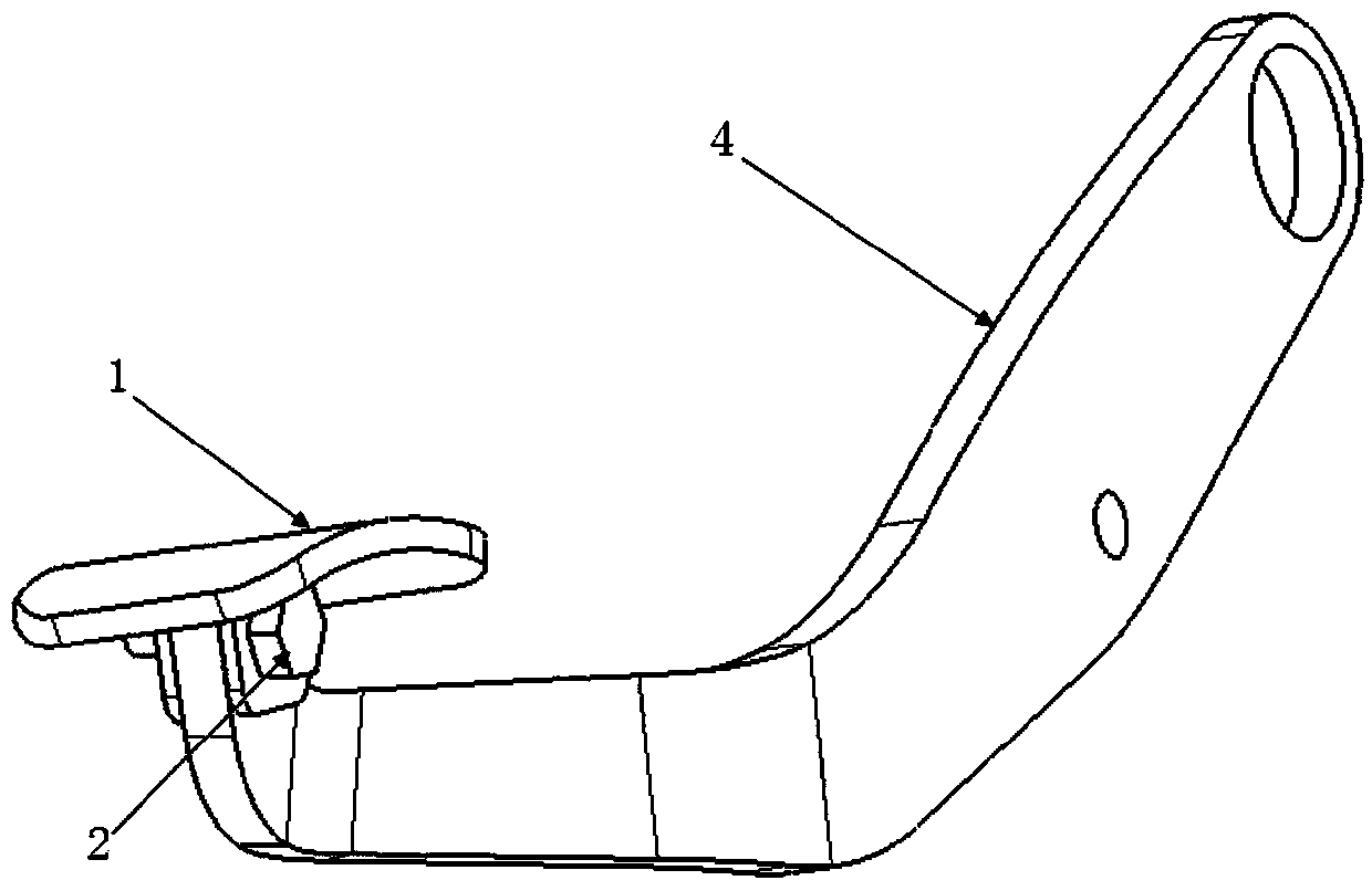

Embodiment Construction

[0027] In order to enable those skilled in the art to better understand the technical solutions of the present invention, the present invention will be further described in detail below in conjunction with the accompanying drawings.

[0028] Such as Figure 2-Figure 8 As shown, a brake pedal assembly provided by the present invention includes a brake pedal arm 4 and a brake pedal 1 installed at the end of the brake pedal arm 4, wherein, in this embodiment, the brake pedal 1 is locked The tightening bolt 2 is installed on the brake pedal arm 4, and the screw rod 21 of the locking bolt 2 is protruded with a plurality of locking teeth 22, and the locking teeth 22 are evenly distributed on the screw rod 21 in the circumferential direction, and the locking teeth 22 are arranged at intervals. One of the purposes of the teeth is to engage and fix, and the other is to locate. Any two locking teeth are arranged at intervals and form a preset angle with each other. Like this, they can r...


PUM


Abstract

The invention discloses a brake pedal assembly which comprises a brake pedal arm and a brake pedal. The brake pedal is installed at the tail of the brake pedal arm and installed on the brake pedal arm through a locking bolt. A plurality of clamping teeth are arranged on a threaded rod of the locking bolt in a protruding mode and distributed on the threaded rod uniformly in the peripheral direction. A first through hole matched with the clamping teeth is formed in the tail of the brake pedal arm. A second through hole matched with the clamping teeth is formed in the connecting part of the brake pedal. When the second through hole rotate around the center, the tooth profile of the second through hole is overlapped with that of the first through hole. After the locking bolt penetrates through the second through hole and the first through hole in sequence, the clamping teeth of the locking bolt are matched with the first through hole and the second through hole synchronously. According to the scheme, the locking bolt with the clamping teeth is adopted and matched with the corresponding fixing holes in the brake pedal arm and the brake pedal, the angle of the brake pedal can be adjusted, and the brake pedal can be replaced.

Description

technical field [0001] The invention belongs to the field of vehicle brake components, and in particular relates to a brake pedal assembly. Background technique [0002] Under normal circumstances, the driver will encounter a situation that requires braking to decelerate while driving. In this case, the most effective and direct action is to step on the brake pedal. Therefore, as one of the important parts of the car, the brake pedal assembly is an indispensable part of the vehicle braking system. The brake pedal assembly is installed in the cab, and is generally assembled on the front wall sheet metal or the bottom plate sheet metal. Although the shape and structure are different according to the design requirements, the main components are basically the same, mainly composed of the brake pedal and the brake pedal. The arm and other parts. [0003] After the existing brake pedal is installed, the overall structure is as follows: figure 1 As shown, it consists of brake pe...

Claims


Application Information

Patent Timeline
IPC IPC(8): B60T7/06
CPCB60T7/06
Inventor 何小波蒋大伟孙琼
Owner ANHUI JIANGHUAI AUTOMOBILE GRP CORP LTD
Learn More