
Safe power line pole

A power pole and safety technology, applied in the direction of safety belts, ladders, life-saving equipment, etc., can solve the problems of ineffective protection of operators, laborious and labor-intensive, and reduced labor efficiency

Active Publication Date: 2016-04-20
PINGDINGSHAN POWER SUPPLY ELECTRIC POWER OF HENAN +1
View PDF8 Cites 27 Cited by
  • Summary
  • Abstract
  • Description
  • Claims
  • Application Information

AI Technical Summary

Problems solved by technology

[0002] With the continuous development of society and the continuous advancement of science and technology, people's living standards are also constantly improving. When living standards improve, people's demand for electricity is also increasing. Among them, in today's life, electric poles It is one of the common electrical equipment. The utility pole can lay the wires at high altitude, which can further protect the wires from being damaged and prevent the occurrence of electric shock problems. When electricians work at heights, they need to use climbing poles. The foot buckle is used to climb the electric pole. When climbing to a high place, the body will be bound to the pole with a safety belt. In the process of climbing with the foot buckle, the foot buckle is too heavy, which will cause laborious and laborious climbing. , thereby reducing labor efficiency, and when the body is tied to the pole, it is easy to fall because the foot buckle is not strong enough or in an accident, because the seat belt is wrapped around the pole, so it will There is a danger of falling along the utility pole, and accidents cannot be avoided even when the body can be firmly fixed on the utility pole. When an accident occurs, it is falling due to its own weight In the process, the safety belt brings a buffer force to the body and hurts itself, so the current safety belt cannot effectively protect the operators working at heights

Method used


Image

  • Safe power line pole
  • Safe power line pole
  • Safe power line pole

Examples


Embodiment Construction

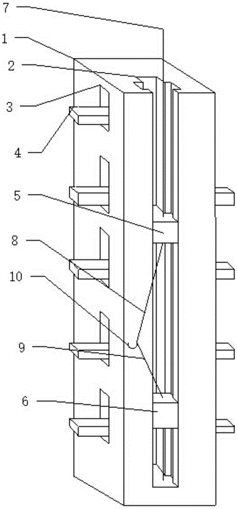
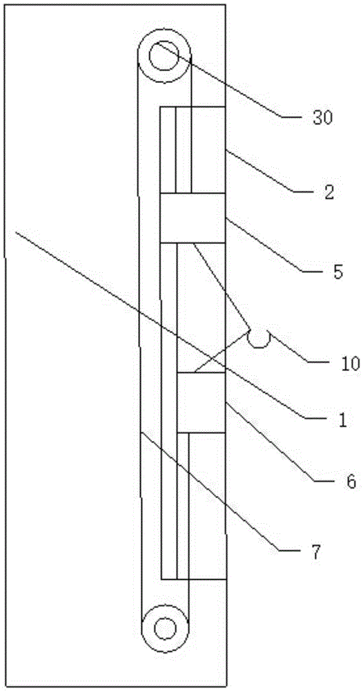
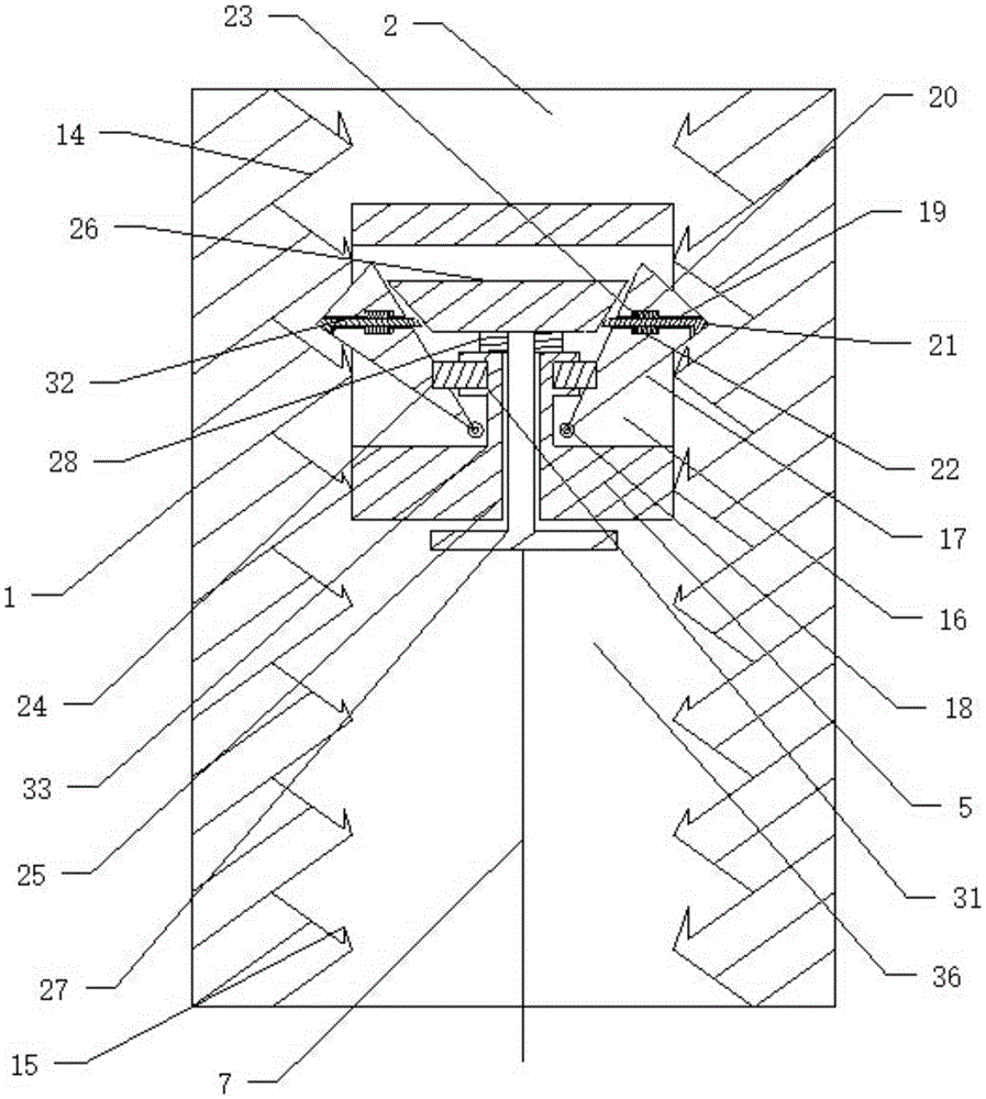
[0028] Such as figure 1 and figure 2 As shown, a safety power pole includes a pole body 1, one side of the pole body 1 includes a cross-shaped main chute 2, and two sides of the main chute 2 are respectively provided with a corresponding side Groove 34 and an inner chute 35 that communicates with described side groove 34, the set roller 30 of two ends is provided with a suspension rope 7 that slides on described roller 30, and described suspension rope 7 two ends are respectively connected with a A safety slider 5 and a T-shaped slider 6, the safety slider 5 is in a cross shape corresponding to the main chute 2 and slides in the main chute 2, wherein as Figure 6 As shown, the T-shaped slider 6 slides in the side grooves 34 provided on both sides of the main chute 2, and the safety slider 5 and the T-shaped slider 6 are respectively connected with a stay rope 8 and b stay rope 9 and a safety hook 10 is connected to the ends of the a stay rope 8 and b stay rope 9, and a zigz...


PUM


Abstract

The invention discloses a safe power line pole. The safe power line pole is characterized in that a main sliding groove which is crossed is formed in one side of a line pole body, a side groove and an inner sliding groove communicated with the same are formed in each of two sides of the main sliding groove, the side grooves are corresponding, a roller is arranged at each of two ends of the main sliding groove, a hanging rope sliding on the rollers is arranged on the rollers at the two ends, two ends of the hanging rope are connected with a safe slider and a T-shaped slider respectively, the safe slider is crossed, corresponds to the main sliding groove and slides in the same, the T-shaped slider slides in the side grooves formed in the two sides of the main sliding groove, the safe slider and the T-shaped slider are connected with a pull rope a and a pull rope b respectively, and the ends of the pull rope a and the pull rope b are mutually connected with a safe hook. The safe power line pole is simple in structure, trouble caused by using of climbers when climbing the power line pole can be avoided, and body safety can be further guaranteed when working aloft.

Description

technical field [0001] The invention relates to a power line pole, in particular to a power line pole for installation, in particular to a fall-proof pole. Background technique [0002] With the continuous development of society and the continuous advancement of science and technology, people's living standards are also constantly improving. When living standards improve, people's demand for electricity is also increasing. Among them, in today's life, electric poles It is one of the common electrical equipment. The utility pole can lay the wires at high altitude, which can further protect the wires from being damaged and prevent the occurrence of electric shock problems. When electricians work at heights, they need to use climbing poles. The foot buckle is used to climb the electric pole. When climbing to a high place, the body will be bound to the pole with a safety belt. In the process of climbing with the foot buckle, the foot buckle is too heavy, which will cause laborio...

Claims


Application Information

Patent Timeline
Patent Type & Authority Applications(China)
IPC IPC(8): E04H12/18E06C9/06E06C7/18
CPCA62B35/00A62B35/0025E04H12/18E06C7/18E06C7/186E06C9/06
Inventor 左常亮
Owner PINGDINGSHAN POWER SUPPLY ELECTRIC POWER OF HENAN
Learn More