Urea condensate pump

A technology of condensate and urea, which is applied in the direction of pumps, pump components, non-variable pumps, etc., can solve problems such as over-temperature and over-pressure that cannot be solved, and achieve the effects of compact structure, convenient installation, and high reliability

Active Publication Date: 2016-04-20
陕西奥维乾元化工有限公司
View PDF5 Cites 1 Cited by
  • Summary
  • Abstract
  • Description
  • Claims
  • Application Information

AI Technical Summary

Problems solved by technology

[0002] At present, the urea chemical industry will produce high-temperature and high-pressure steam during the production process, and it is necessary to cool the urea steam to prevent the occurrence of over-temperature and over-pressure hazards. The current condensation generally uses pumps to transport condensing media for cooling, which cannot solve the problem of over-pressure in the production process. The temperature overpressure problem

Method used


Image

  • Urea condensate pump

Examples


Embodiment Construction

[0028] The present invention will be further described in detail below in conjunction with the accompanying drawings.

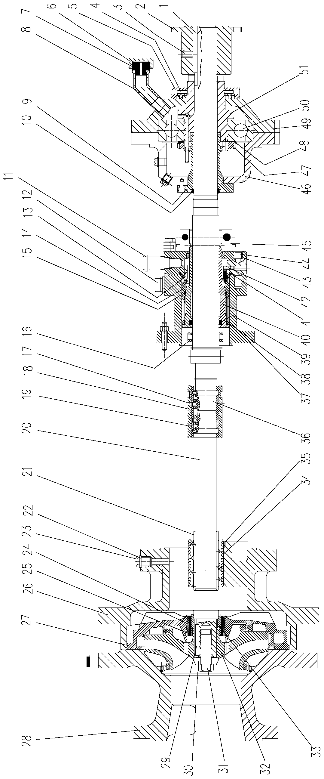
[0029] Such as figure 1 As shown, a urea condensate pump of the present invention includes a first shaft 20 and a second shaft 36 coaxially arranged, and the right end of the first shaft 20 and the left end of the second shaft 36 are detachably connected together.

[0030] Among them, the first key 1 is installed on the right end of the second shaft 36; the coupling 2 is connected with the second shaft 36 through the first key 1, so as to realize the circumferential fixation between the second shaft 36 and the coupling 2 to transmit torque , and tightened with the first screw 3, so as to play the role of axial fixation; the sealing ring 5 is installed on the third shaft sleeve 51, and fastened with the set screw 4, which exerts a force on the sealing ring 5, thereby It plays a sealing role and improves the sealing effect, which belongs to the mechanical seal...


PUM


Abstract

The invention discloses a urea condensate pump. The pump comprises a first shaft and a second shaft which are arranged coaxially, wherein the right end of the first shaft is detachably connected with the left end of the second shaft; a bearing sleeve, a third shaft sleeve and a couplingsleevesthe second shaft in sequence from the left end of the second shaft; a bearing seat and a bearing seat end cover connected with the bearing seat sleeve the bearing sleeve and the third shaft sleeve separately; a bearing sleeves the third bearing sleeve, and the axial movement of the bearing along the third shaft sleeve is limited by a round nut; the bearing seat end covercommunicateswith a bend pipe; the second shaft is sleeved by a stopper ring, a second shaft sleeve and a fixed sleeve from the left end to the right end; the second shaft sleeve is sleeved by a first shaft sleeve, a spring, a movable ring, a static ring and a cooling sleeve from the left end to the right end; a first pipe joint communicatingwith the side wall of the cooling sleeve is a coolant inlet, a second pipe joint communicatingwith the side wall of the first shaft sleeve is an outlet; a pump port, an impeller sleeve, an impeller and a medium shell sleeve the first shaft in sequence from the left end; a diversion disk communicating with the pump outlet sleeves the impeller sleeve by the bearing; and the axial movement of the impeller along the first shaft is limited by a fourth screw.

Description

Technical field: [0001] The invention relates to a urea condensate pump, which is used for transporting cooling liquid in the process of urea processing. Background technique: [0002] At present, the urea chemical industry will produce high-temperature and high-pressure steam during the production process, and it is necessary to cool the urea steam to prevent the occurrence of over-temperature and over-pressure hazards. The current condensation generally uses pumps to transport condensing media for cooling, which cannot solve the problem of over-pressure in the production process. temperature overpressure problem. Invention content: [0003] The object of the present invention is to provide a urea condensate pump aiming at the problems existing in the prior art. [0004] In order to achieve the above object, the present invention adopts following technical scheme to realize: [0005] A urea condensate pump, comprising a first shaft and a second shaft coaxially arranged,...

Claims


Application Information

Patent Timeline
Patent Type & Authority Applications(China)
IPC IPC(8): F04D29/043F04D29/044F04D29/58F04D29/10
CPCF04D29/043F04D29/044F04D29/106F04D29/586
Inventor 栾飞刘浩钱杰王强魏引焕
Owner 陕西奥维乾元化工有限公司
Why Eureka
Try Eureka