
Installation oil groove for vane pumps

A vane pump and oil tank technology, which is applied to the components, pumps, and pump components of the pumping device for elastic fluid, can solve the problems of easy cleaning and damage, and achieve the effect of protecting health, avoiding damage and draining oil. Good results

Inactive Publication Date: 2016-04-20
CHONGQING YONGCHUAN DISTRICT YIRUI MACHINERY
View PDF0 Cites 0 Cited by
  • Summary
  • Abstract
  • Description
  • Claims
  • Application Information

AI Technical Summary

Problems solved by technology

However, it is not easy to clean the hands directly with engine oil like this, and at the same time, such operation will cause damage to people's hands for a long time

Method used


Image

  • Installation oil groove for vane pumps

Examples


Embodiment Construction

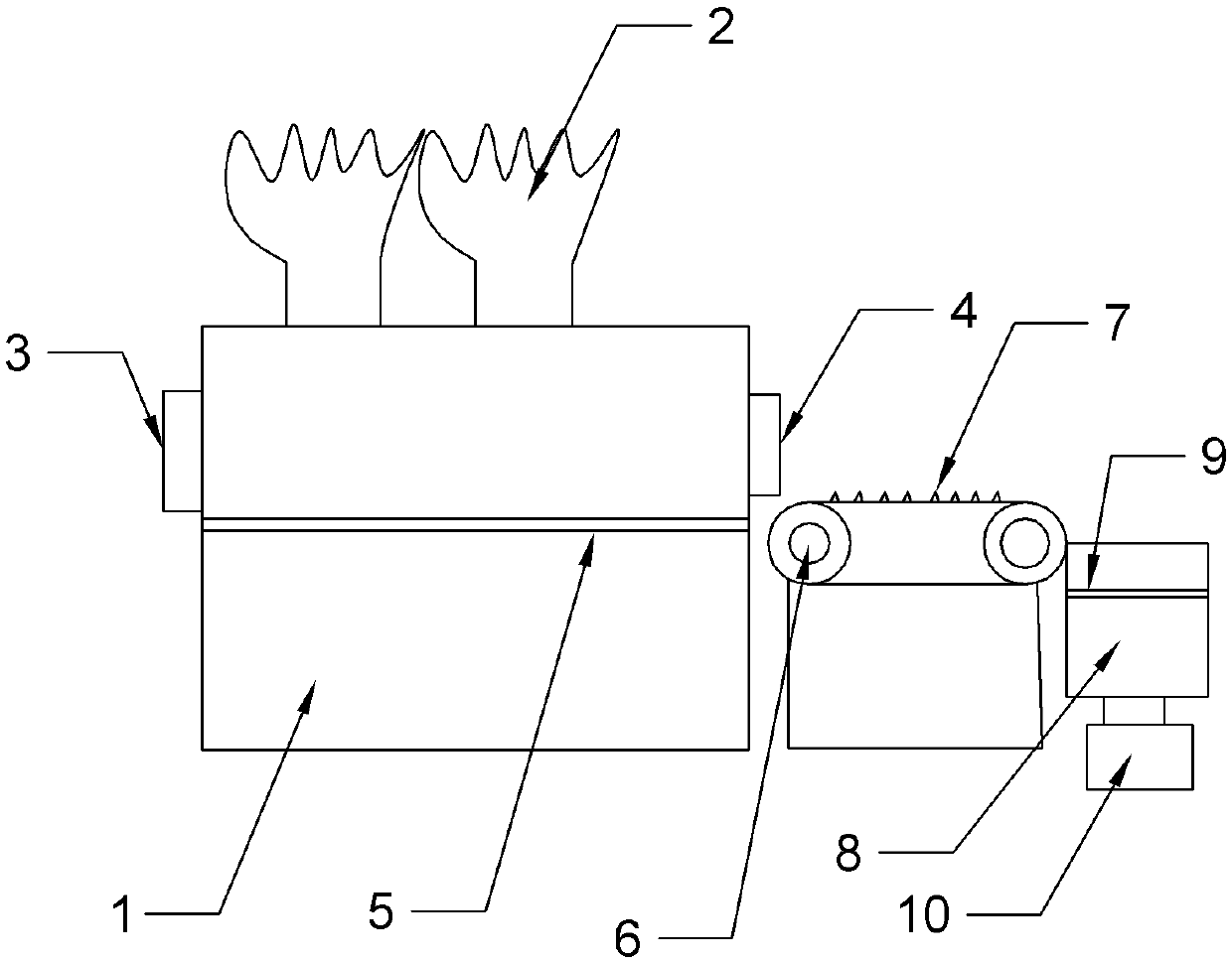
[0014] The marks in the accompanying drawings of the present invention are: oil tank body 1, gloves 2, feed port 3, discharge port 4, operating platform 5, transmission mechanism 6, protrusion 7, oil drain barrel 8, filter screen 9, motor 10 .

[0015] Such as figure 1 As shown, the installation oil tank for the vane pump includes the oil tank body 1. Two gloves 2 are arranged above the oil tank body 1. The gloves 2 are made of leather materials. The gloves 2 and the oil tank body 1 are connected through the installation pipe, so that It is convenient for people to access the vane pump through the oil tank body 1 in reverse. The side wall of the oil tank body 1 is provided with a material inlet 3, and the corresponding side wall of the oil tank body 1 is provided with a discharge port 4. The oil tank body 1 is provided with an operation platform 5, and an oil passage hole is arranged on the operation platform 5, and the oil passage hole Arranged in a uniform matrix, so that ...


PUM


Abstract

The invention relates to the field of vane pumps, in particular to an installation oil groove for the vane pumps. The installation oil groove comprises an oil groove body, two gloves are arranged above the oil groove body, a feed hole is formed in the side wall of the oil groove body, a discharge hole is formed in the corresponding side wall of the oil groove body, an operation platform is arranged in the oil groove body, through oil holes are formed in the operation platform, a conveying mechanism is arranged on the discharge hole, an oil dripping bucket is arranged at the end of the conveying mechanism, a filter net is arranged in the oil dripping bucket, and a motor is arranged at the lower end of the oil dripping bucket. According to the invention, people do not need to directly apply engine oil to the hands, the hands are protected, and the assembly effect is good.

Description

technical field [0001] The invention relates to the vane pump field, in particular to an installation oil groove for the vane pump. Background technique [0002] The vane pump is a pump in which the vanes in the rotor groove are in contact with the pump casing, and the sucked liquid is pressed from the oil inlet side to the oil discharge side. The pump is composed of components such as rotor, stator, vane, oil distribution plate and end cover. The inner surface of the stator is a cylindrical hole, and there is an eccentricity between the rotor and the stator. The blades can slide flexibly in the groove of the rotor. Under the action of the centrifugal force of the rotor and the pressure oil flowing into the root of the blades, the top of the blades is close to the inner surface of the stator, so that the two adjacent blades, the oil distribution plate, the stator and the rotor A sealed working chamber is formed between them. When the rotor rotates counterclockwise, the bl...

Claims


Application Information

Patent Timeline
Patent Type & Authority Applications(China)
IPC IPC(8): F04D29/60
CPCF04D29/605
Inventor 王明安
Owner CHONGQING YONGCHUAN DISTRICT YIRUI MACHINERY
Learn More