Camera lens clamping device

A clamping device and lens technology, applied in the directions of optics, instruments, camera bodies, etc., can solve the problem that the lens clamping mechanism cannot be adjusted in direction, and achieve the effect of improving efficiency and reducing debugging work.

Active Publication Date: 2016-04-20
CETC BEIJING ELECTRONICS EQUIP
View PDF11 Cites 2 Cited by
  • Summary
  • Abstract
  • Description
  • Claims
  • Application Information

AI Technical Summary

Problems solved by technology

[0006] In order to overcome the technical problem that the lens clamping mechanism of the detection chip cannot be adjusted in the prior art, the present invention provides a lens clamping device

Method used


Image

  • Camera lens clamping device
  • Camera lens clamping device
  • Camera lens clamping device

Examples


Embodiment Construction

[0063] In order to make the object, technical solution and advantages of the present invention clearer, the present invention will be described in detail below with reference to the accompanying drawings and specific embodiments.

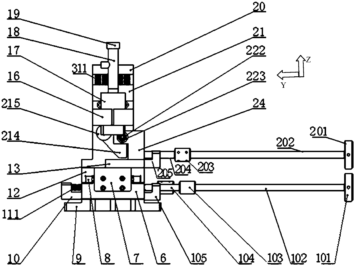
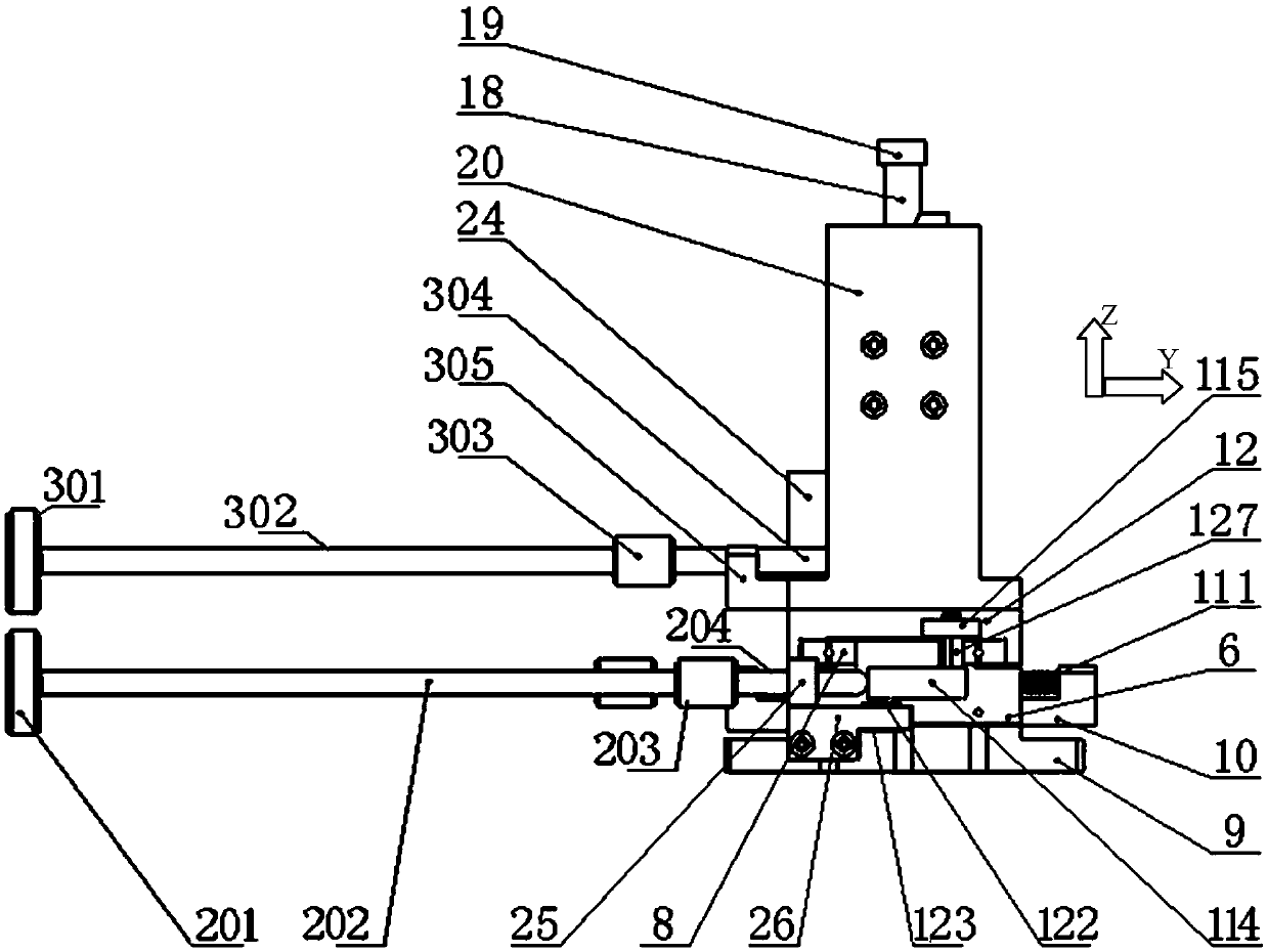
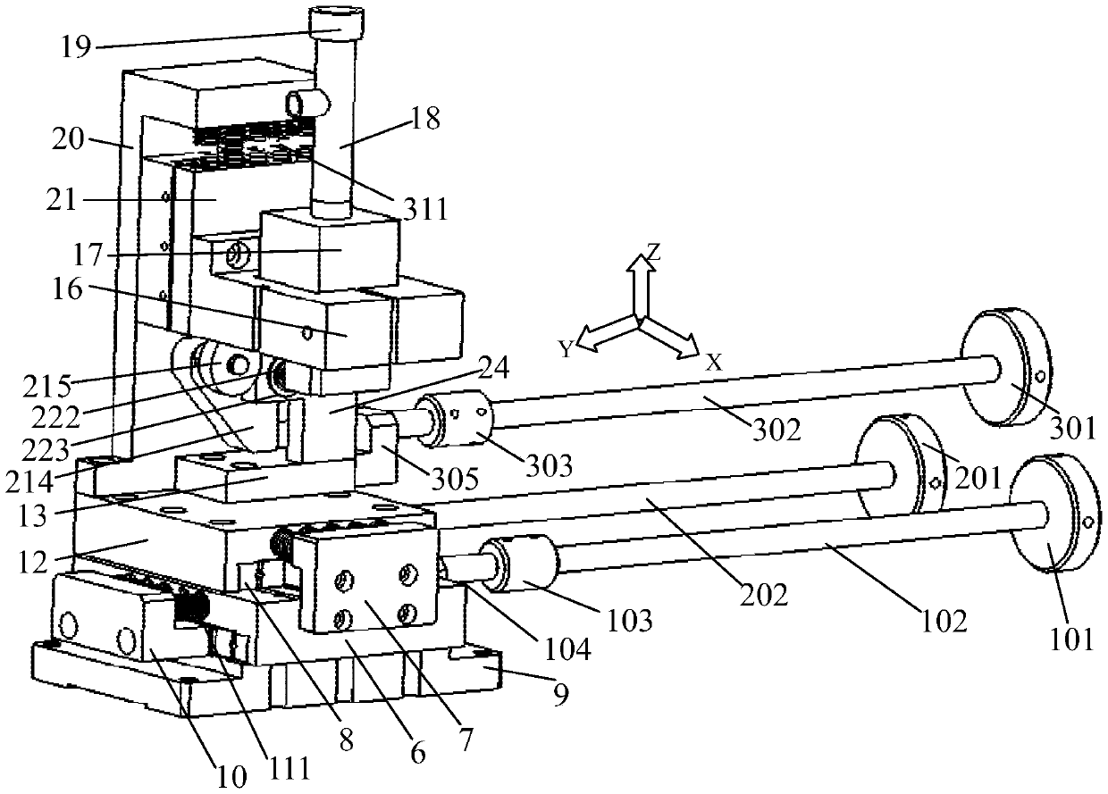
[0064] refer to Figure 1 to Figure 6 As shown, the present invention provides a lens clamping device, comprising: a base 9; a first sliding seat 6, which is slidably arranged on the base 9 along a first horizontal direction; a first driving mechanism, driven by the first sliding seat 6 Connected, the first driving mechanism drives the first sliding seat 6 to move along the first direction; the second sliding seat 12 is slidably arranged on the first sliding seat 6 along the second horizontal direction; the second driving mechanism and the second sliding seat 12 drive connection, the second driving mechanism drives the second sliding seat 12 to move along the second direction; the vertical spring seat 20 is erected and fixed on the second sliding se...


PUM


Abstract

The invention provides a camera lens clamping device which comprises a base, a first slide base, a first drive mechanism, a second slide base, a second drive mechanism, a vertical spring seat, a third slide base, a third drive mechanism and a clamping mechanism, wherein the first drive mechanism is in sliding connection to the first slide base; the first drive mechanism drives the first slide base to move in a first direction; the second slide base is arranged on the first slide base in a sliding mode in a horizontal second direction; the second drive mechanism is in driving connection to the second slide base; the second drive mechanism drives the second slide base to move in a second direction; the vertical spring seat is vertically fixed to the second slide base; the third slide base is arranged on the vertical spring seat in the sliding mode in a vertical direction; the third drive mechanism is in driving connection to the third slide base, and the third drive mechanism drives the third slide base to move in the vertical direction; and the clamping mechanism is mounted on the third slide base, and is used for clamping a camera lens. The camera lens clamping device provided by the invention can regulate the clamped camera lens in three directions, so that the device can meet back detection of chips of different sizes. Besides, the device reduces debugging work of an operator, and greatly improves the detecting efficiency.

Description

technical field [0001] The invention relates to the field of semiconductor manufacturing, in particular to a lens clamping device. Background technique [0002] In the field of semiconductor manufacturing such as chips, many equipment manufacturers have high requirements for the upper surface of the chip. Through image recognition on the upper surface of the chip, the quality of the chip can be distinguished. However, in the prior art, this method has the following disadvantages: [0003] 1) After the current process is completed, it is impossible to detect whether the back of the chip is damaged. This will affect the subsequent processing and use of the chip. [0004] 2) During the production process, the chip types and sizes are different, and the positions in the X, Y, and Z directions need to be adjusted frequently. The traditional lens clamping mechanism is only aligned to the center through mechanical assembly, and the position is fixed. During the detection proces...

Claims


Application Information

Patent Timeline
Patent Type & Authority Applications(China)
IPC IPC(8): F16M11/04F16M11/18G03B17/56
CPCG03B17/561F16M11/043F16M11/18F16M2200/08
Inventor 刘亚奇郝靖李鹏飞
Owner CETC BEIJING ELECTRONICS EQUIP
Why Eureka
Try Eureka