Critical field force inducing operation controller

A technology of controllers and potentiometers, applied in adaptive control, mechanical pressure/force control, general control systems, etc., can solve problems such as failure to meet requirements, and achieve the effect of less debugging work, simple form, and good linearity

Inactive Publication Date: 2005-03-30
NANKAI UNIV
View PDF0 Cites 0 Cited by
  • Summary
  • Abstract
  • Description
  • Claims
  • Application Information

AI Technical Summary

Problems solved by technology

Therefore, the application of this device in an environment that requires a small volume, a straight line or an arc, and a strict linear relationship between the force feeling and the excitation current within a certain range cannot meet the requirements.

Method used


Image

  • Critical field force inducing operation controller
  • Critical field force inducing operation controller
  • Critical field force inducing operation controller

Examples


Embodiment Construction

[0036] The present invention is described in detail below in conjunction with each figure:

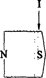
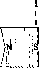
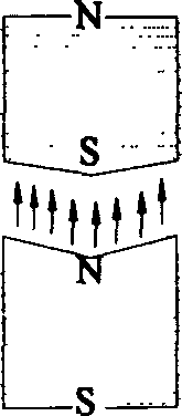
[0037] The present invention is made up of following main parts, and the frame mechanism f1 of this device is installed on the swing lever L2 of the front end of the upper wall of the frame mechanism in the form of a movable shaft, and the swing lever can be as follows Figure 9Swing in the direction shown, the range of motion is not less than 40 degrees. There is a finger collar O3 at the lower end of the swing lever, which is used for operator's finger operation. A rectangular coil frame K0 4 with a cylindrical surface shape is fixedly installed in the center of the swing rod, and enameled wire is wound on the coil frame to form a cylindrical movable coil L0 5, which moves together with the swing rod. On the left side of the swing rod, two magnetic poles M1 6, M2 7 are installed according to a certain inclination, among which M1 is located at the top and M2 is located at the bottom;...


PUM


Abstract

The present invention relates to robot controller and is especially mini controller in master-slave operation mode in robot system. The mini controller includes frame with swinging rod in the upper part, finger ring in the lower part and inducing coil on the swinging rod; and two electromagnetic poles with winding on two sides of the frame. Between the two cylindrical surfaces of the electromagnetic poles and separated by not greater than 5 mm, the winding is embedded to produce moment signal on electromagnetic induction for the control of the slave manipulator. The present invention features compact structure, small volume, relatively greater and stable moment signal, and is especially suitable for use in small and miniature control device to provide force or moment feedback information and to make the operator to on-scene feeling.

Description

technical field [0001] The invention relates to a robot operation controller, in particular to a micro operation controller with a master-slave operation hand in a robot system. Background technique [0002] This master-slave robot system is composed of two parts: master hand and slave hand. When working, the operator grasps the main operating handle of the robot, and instructs the slave hand of the robot to perform certain operations by controlling the moving device on the main handle. The slave hand of the robot completes various tasks according to the commands issued by the master hand of the robot; at the same time, when the slave hand of the robot is working, the force sensor installed on the slave hand will receive the force (moment) It is converted into an electrical signal and transmitted to the main hand of the robot. There should be a specific device on the main hand of the robot to convert the electrical signal of the force (torque) transmitted by the robot from ...

Claims


Application Information

Patent Timeline
Patent Type & Authority Patents(China)
IPC IPC(8): B25J3/00G05B13/02G05D3/12G05D15/01
Inventor 张建勋李彬王树新安刚
Owner NANKAI UNIV
Why Eureka
Try Eureka