Transformer installation device with sliding chute

A technology for installing a device and a transformer, which is applied in the field of transformers and can solve the problems of complicated operation, limited convenience and rapidity of operation, and difficulty in clearly locking the bolt operation in place.

Inactive Publication Date: 2016-04-20
方德兰
View PDF7 Cites 2 Cited by
  • Summary
  • Abstract
  • Description
  • Claims
  • Application Information

AI Technical Summary

Problems solved by technology

However, the locking of such a pivoting door is often carried out by using a manually operated locking bolt, which makes the operation complicated. In addition, the convenience and quickness of operation are limi

Method used


Image

  • Transformer installation device with sliding chute
  • Transformer installation device with sliding chute
  • Transformer installation device with sliding chute

Examples


Embodiment Construction

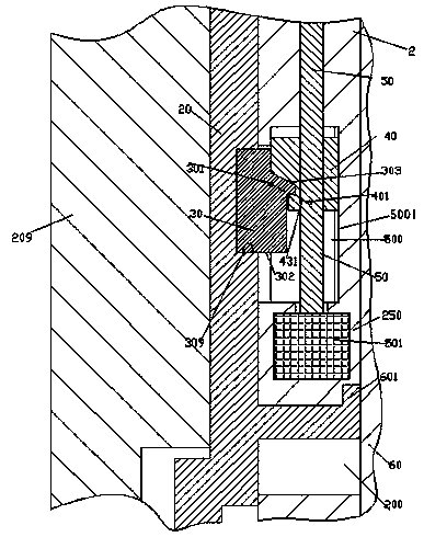
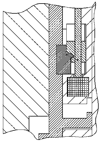
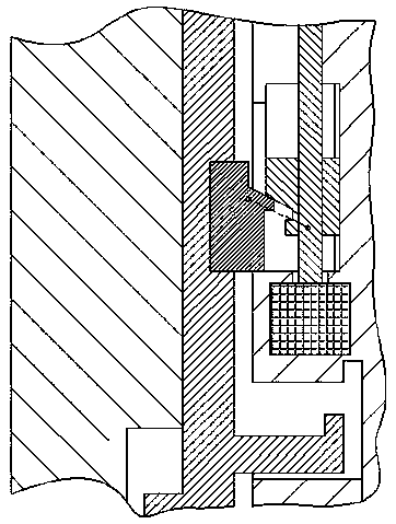
[0013] Combine below Figure 1-6 The present invention will be described in detail.

[0014] According to an embodiment, a transformer installation device with a chute is used to hermetically surround and accommodate a transformer 208 ), comprising a main housing case 2 ) and a pivot that removably covers the opening of the main housing case 2 ). The pivoting door device 209), the first side of the pivoting door device 209) is hinged on the main housing case 2), and the second side is openably and closably engaged with the main housing case 2), Wherein, the pivoting door device 209) is slidably installed on the second side with an engaging locking bolt device 20), and the engaging locking bolt device is integrally arranged facing the main housing case 2). There is a locking hook 60) for extending into the recessed hole 200) in the wall of the main housing case 2) and is achieved by engaging the hook end 601) with the inner undercut of the recessed hole 200). The pivoting doo...


PUM


Abstract

The invention discloses a transformer installation device with a sliding chute. The transformer installation device is used for encircling and accommodating a transformer (208) in a closed manner, and comprises a main accommodating shell (2) and a pivoting door device (209), wherein the pivoting door device (209) removably covers the opening of the main accommodating shell (2); the first side edge of the pivoting door device (209) is hinged to the main accommodating shell (2); the second side edge of the pivoting door device (209) is jointed with the main accommodating shell (2) in a manner of being capable of being opened and closed; a joint locking bolt device (20) is arranged at the second side edge of the pivoting door device (209) in a manner of being capable of sliding up and down; the joint locking bolt device (20) faces to the main accommodating shell (2), and is integrally provided with a locking hook body (60) which is used for locking the pivoting door device (209) onto the main accommodating shell (2) by means of extending into a concave hole (200) in the wall part of the main accommodating shell (2) and jointing with the inside undercut part of the concave hole (200) through a hook part tail end (601).

Description

technical field [0001] The invention relates to the field of transformers, in particular to a transformer installation device with a chute. Background technique [0002] In industrial applications, transformers are often placed on site to provide power. In order to ensure the operating environment of transformer equipment, it is usually placed in a transformer-specific installation device, such as a transformer cabinet. [0003] The pivoting door arrangement of such installations is often required to be easily opened for maintenance of the transformer equipment. Existing pivoting door devices often adopt a hinged way to open. However, the locking of such a pivoting door is often performed by a manually operated locking bolt, which makes the operation complicated, and in addition, the convenience and quickness of operation are limited and affected. However, in some power-operated locking bolt applications, it is difficult for the operator to know when the locking bolt is i...

Claims


Application Information

Patent Timeline
IPC IPC(8): H01F27/02E05B47/02E05B65/52E05F15/616
CPCH01F27/022E05B47/0012E05B47/026E05B65/5238E05B2047/0016
Inventor 方德兰
Owner 方德兰
Why Eureka
Try Eureka