Staple abutting seat component and tubular anastomat adopting same

A technology of anvils and components, which is applied in the field of medical devices and can solve problems such as anastomotic damage

Active Publication Date: 2016-04-27
TIANJIN ONEHEALTH MEDICAL INSTR CO LTD
View PDF6 Cites 4 Cited by
  • Summary
  • Abstract
  • Description
  • Claims
  • Application Information

AI Technical Summary

Problems solved by technology

[0005] The invention provides a side-downable nail anvil assembly to at least solve the technical problem that the nail anvil will cause damage to the anastomosis when the instrument is fired and passes through the anastomosis

Method used


Image

  • Staple abutting seat component and tubular anastomat adopting same
  • Staple abutting seat component and tubular anastomat adopting same
  • Staple abutting seat component and tubular anastomat adopting same

Examples


Embodiment 1

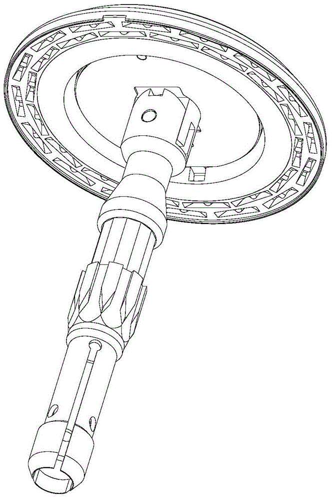
[0045] This embodiment provides an optional figure 1 Anvil assembly shown, including as figure 2 The shown nail anvil base 1, such as image 3 Shown center rod 2, such as Figure 4 Stroke block 3 as shown and as Figure 5 The shown nail anvil torsion spring 4.

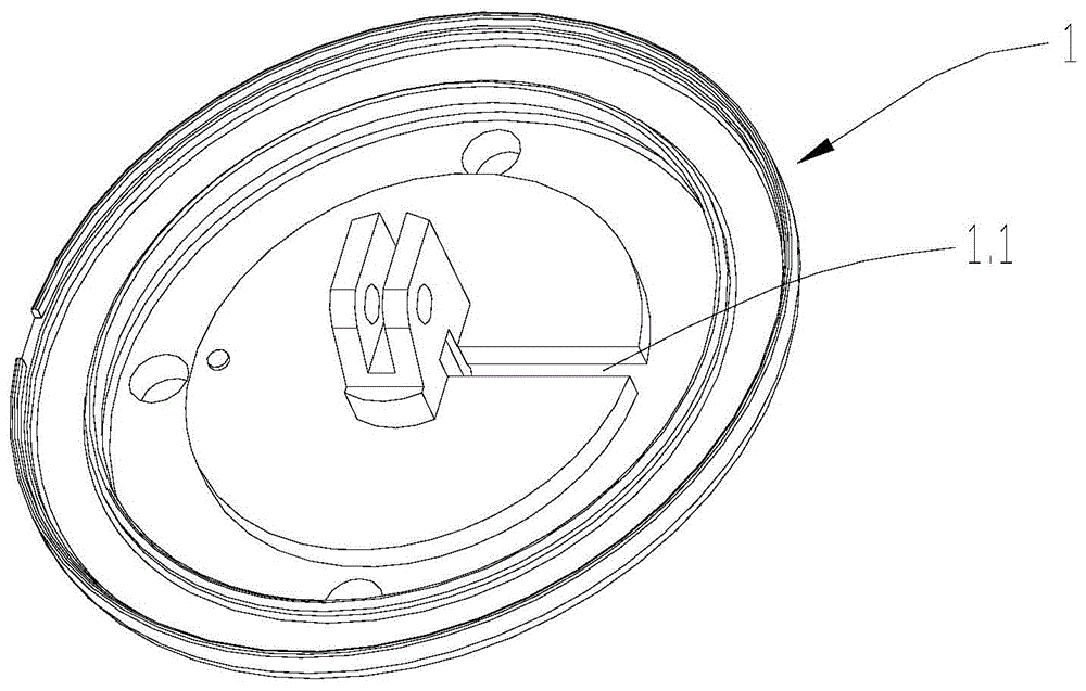
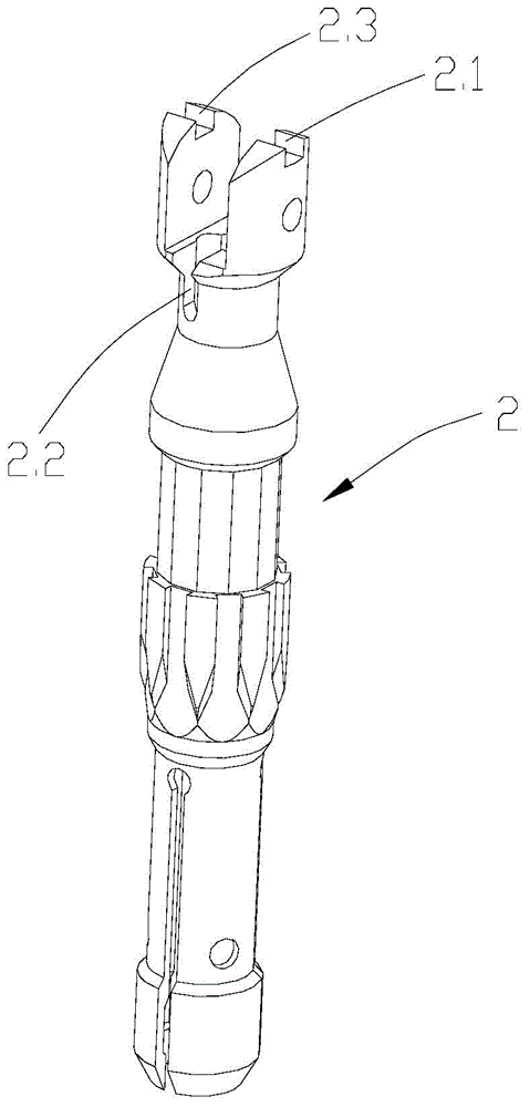
[0046] Such as figure 2 As shown, the above-mentioned nail anvil base 1 is provided with a chute 1.1, such as image 3 As shown, the above-mentioned central rod 2 is provided with a first groove 2.1 and a second groove 2.2, and the groove 2.3 symmetrical to the above-mentioned first groove 2.1 may or may not be present, as Figure 8 As shown, the above-mentioned anvil base 1 is connected with the above-mentioned central rod 2 through the rotation of the abutment pin 1.2, as shown in FIG. Figure 4 As shown, one end of the above stroke block 3 is provided with a head protrusion 3.1, and the above stroke block 3 is slidably installed on the above chute 1.1 of the above nail anvil base 1.

[0047] Such as Image...

Embodiment 2

[0055] This embodiment provides an optional Figure 21 A tubular stapler is shown, and the tubular stapler includes any one of the aforementioned nail anvil assemblies.

[0056] In an initial state, the protrusion of the head of the stroke block is located in the first groove of the central rod, so that the base of the nail anvil is kept perpendicular to the central rod.

[0057] When the above-mentioned cutting knife cuts through the above-mentioned spacer ring, it shows that the cutting tissue has been completed. At this time, the above-mentioned cutter continues to move forward, and the above-mentioned stroke block is pushed to translate. When the head of the above-mentioned stroke block protrudes away from the above-mentioned first groove of the above-mentioned center rod, the above-mentioned nail abutment seat base is pressed against the torsion spring or plate of the nail abutment seat. Falling sideways under the action of the spring.


PUM


Abstract

An embodiment of the invention provides a staple abutting seat component which comprises a staple abutting seat base, a central rod, a stroke block and a staple abutting seat elastic part. The staple abutting seat base is provided with a sliding groove, the central rod is provided with a first groove and a second groove, the staple abutting seat base and the central rod are rotatably connected through a staple abutting seat pin, a head protrusion is arranged at one end of the stroke block, the stroke block is slidably mounted in the sliding groove of the staple abutting seat base, and when the head protrusion is in the first groove of the central rod, the stroke block enables the staple abutting seat base to be perpendicular to the central rod; an elbow end of the staple abutting seat elastic part is abutted against the staple abutting seat base, and a straight handle end of the staple abutting seat elastic part is abutted in the second groove of the central rod. The embodiment of the invention further provides a tubular anastomat adopting the staple abutting seat component which can laterally topple.

Description

technical field [0001] The present invention relates to medical equipment, and more specifically, to a nail anvil assembly and a tubular stapler using the nail anvil assembly. Background technique [0002] In surgical operations, medical staplers have become an indispensable auxiliary medical device in the process of suturing human tissue. With the development of medicine and product research and development, more and more multifunctional staple products are used in clinical practice. One of the few tools. The application of medical stapler has many advantages such as less bleeding during operation, shorter operation time, reduction of manual operation error, avoidance of infection, and quick recovery of postoperative function. [0003] The tubular stapler is one of the more commonly used medical staplers, and is used for end-to-end, end-to-side, and side-to-side anastomosis. [0004] After most of the existing tubular staplers are fired, the anvil and the trocar are in a...

Claims


Application Information

Patent Timeline
Patent Type & Authority Applications(China)
IPC IPC(8): A61B17/115
Inventor 孙景荣
Owner TIANJIN ONEHEALTH MEDICAL INSTR CO LTD
Why Eureka
Try Eureka