Punching device

A technology of punching dies and punches, which is applied in the direction of presses, metal processing equipment, safety equipment, etc., can solve problems affecting product accuracy, poor safety, and bulky volume, so as to reduce safety accidents, product consistency, and safety The effect of high coefficient

Inactive Publication Date: 2016-04-27
ZHANGJIAGANG XUJUN MACHINERY PARTS CO LTD
View PDF10 Cites 6 Cited by
  • Summary
  • Abstract
  • Description
  • Claims
  • Application Information

AI Technical Summary

Problems solved by technology

[0002] The traditional punching machine uses a motor to drive the cam to drive the punching head. This kind of punching machine is bulky, bulky and noisy. The stroke of the punching head is long and cannot be stopped after being triggered. It often hurts the operator's hand, and the safety is poor.
Only one part of the stamping process can be completed at a time, and multiple positioning is required for multi-process stamping, which affects product accuracy; in addition, the equipment consumes a lot of energy

Method used


Image

  • Punching device

Examples


Embodiment Construction

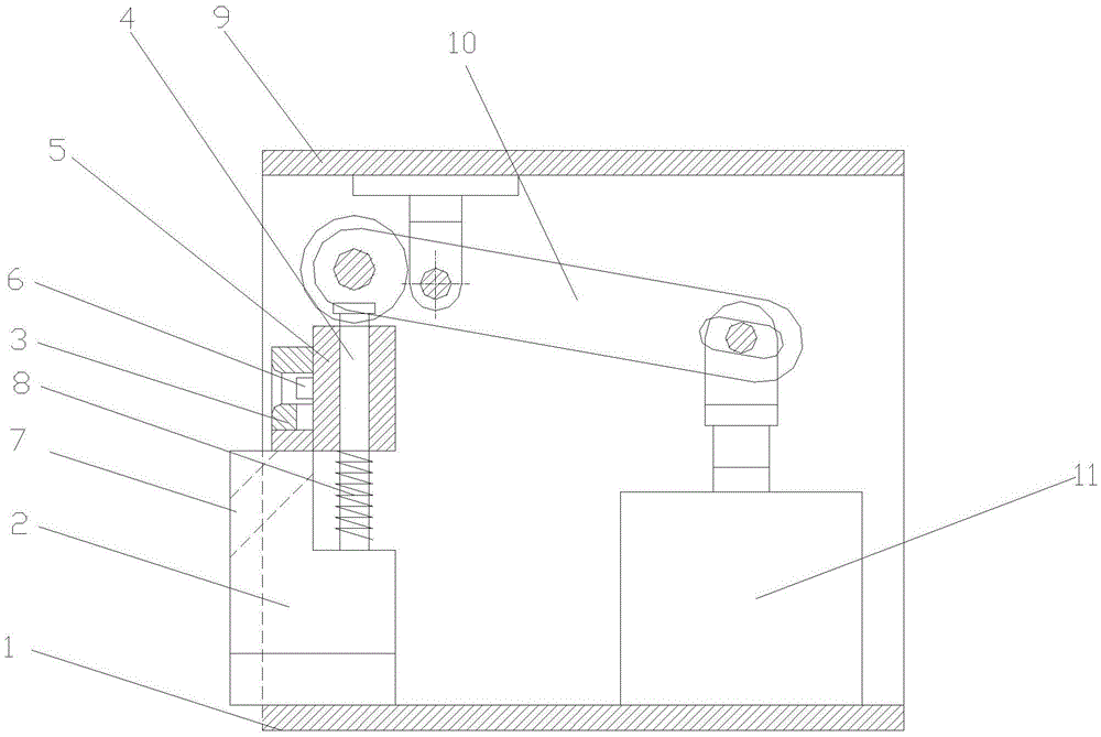
[0011] Specific embodiments of the present invention will be described in detail below in conjunction with the accompanying drawings.

[0012] like figure 1 As shown, a punching device includes a base 1, a mounting base 2 is provided on the base 1, a filling mold 3 is provided on the mounting base 2, two guide rods 4 are provided on the mounting base 2, and the guide rod 4 The upper cover is provided with a punching die 5 that can move up and down, and the punching die 5 is provided with a punch 6 . The mounting base 2 is provided with a punching waste discharge hole 7 . The part of the guide rod 4 between the mounting base 2 and the punching die 5 is provided with a return spring 8 for lifting the punching die 5 upwards and resetting. The base 1 is provided with a stand 9, and the lower surface of the stand 9 is hinged with a lever 10 for pressing down the punching die 5. One end of the lever 10 is located above the punching die 5, and the other end of the lever 10 is arran...


PUM


Abstract

The invention discloses a punching device. The punching device comprises a substrate. An installation base is arranged on the substrate. A material containing die is arranged on the installation base. A punching die capable of moving up and down is arranged on the installation base. A plunger chip is arranged on the punching die. A plurality of reset springs used for ejecting the punching die upwards to reset are arranged between the installation base and the punching die. A floor stand is arranged on the substrate. A lever used for pressing down the punching die is hinged to the lower surface of the floor stand. One end of the lever is located above the punching die, and the other end of the lever is hinged to a piston rod of an air cylinder which is arranged on the floor stand or the substrate and used for driving the lever. The punching device is simple in structure and convenient to use.

Description

technical field [0001] The invention relates to a punching device. Background technique [0002] The traditional punch press uses a motor to drive the cam to drive the punch to punch. This kind of punch equipment is bulky, bulky and noisy. The stroke of the punch is long and cannot be stopped after triggering. It often hurts the operator's hand and has poor safety. Only one part of the stamping process can be completed at a time, and multiple positioning is required for multi-process stamping, which affects product accuracy; in addition, the equipment consumes a lot of energy. Contents of the invention [0003] The technical problem to be solved by the present invention is to provide a punching device with simple structure and convenient use. [0004] In order to solve the above technical problems, the technical solution adopted in the present invention is: a punching device, including a base, a mounting seat is provided on the base, a material filling mold is provided on...

Claims


Application Information

Patent Timeline
Patent Type & Authority Applications(China)
IPC IPC(8): B21D28/02B21D28/20B21D55/00B30B15/04
CPCB21D28/02B21D28/20B21D55/00B30B15/041
Inventor 蒋伟
Owner ZHANGJIAGANG XUJUN MACHINERY PARTS CO LTD
Why Eureka
Try Eureka