
Bale Opener

A technology of unpacking machine and main shaft, applied in conveyors, transportation and packaging, fiber unpacking, etc., can solve the problems of wear, complex structure of lifting mechanism, complex precise orientation of fiber packages, etc.

Inactive Publication Date: 2016-04-27
MASCHINENFABRIK RIETER AG
View PDF11 Cites 2 Cited by
  • Summary
  • Abstract
  • Description
  • Claims
  • Application Information

AI Technical Summary

Problems solved by technology

[0007] A disadvantage of the disclosed design according to the prior art is the complex construction of the lifting mechanism, which makes it necessary to provide a suspension independent of the actual movement, or the lifting mechanism has to have several lifting drives to move the stripping arm simultaneously
The precise orientation of the stripping arm relative to the fiber bale to be unpacked is therefore complicated and has to be readjusted periodically due to wear caused by the operation
In addition, complex sensor systems are required to position and control the lifting mechanism

Method used


Image

  • Bale Opener
  • Bale Opener
  • Bale Opener

Examples


Embodiment Construction

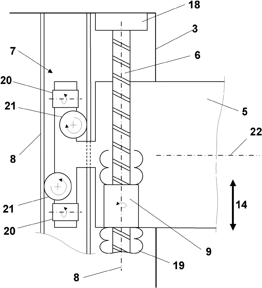
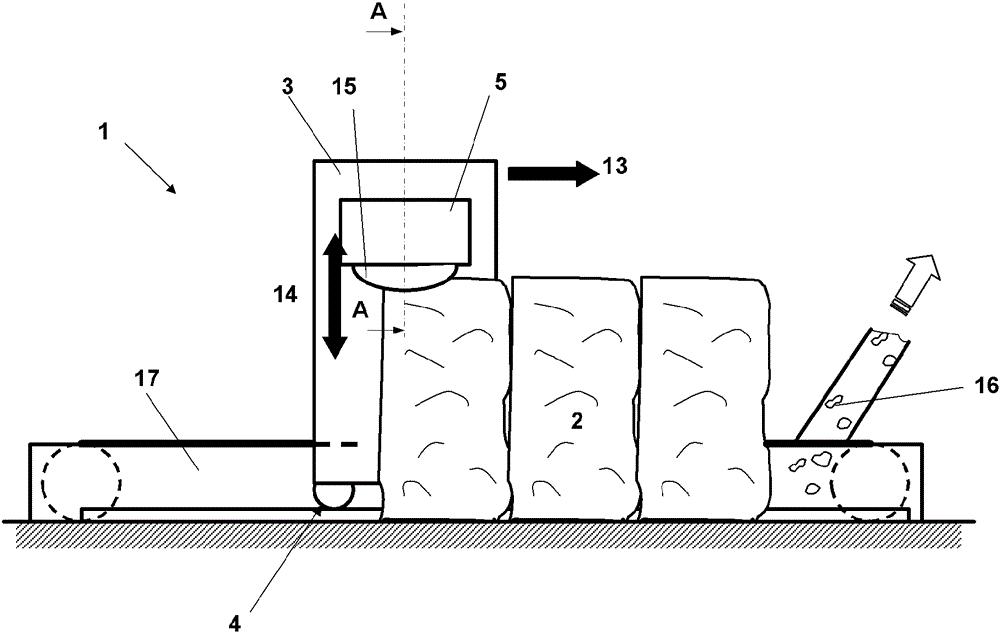
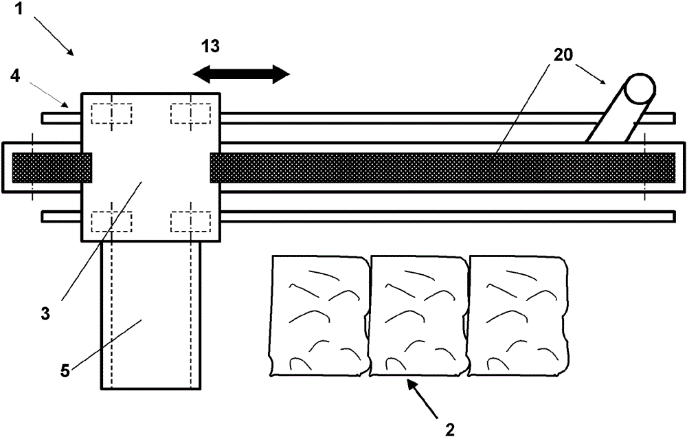
[0029] figure 1 with figure 2 A schematic diagram of a bale unpacking machine 1 for stripping fiber bundles 2 is shown. figure 1 The unpacking machine 1 is shown in plan view and figure 2The unpacking machine 1 is shown in a view. The bag unpacking machine 1 basically consists of a stripping tower 3 and a stripping arm 5 . The stripping arm 5 is fastened on one side to the stripping tower 3 and is arranged to hang freely above the fiber bale 2 . The stripping tower 3 is equipped with a horizontal drive 4 . The stripping tower 3 moves on rails along the fiber pack 2 by means of a drive mechanism 4 . The stripping arm 5 mounted on the stripping tower 3 is guided over the surface of the fiber bale 2 by means of this movement 13 . A stripping unit (typically one or more stripping rollers 15 ) is provided in the stripping arm 1 . Stripping rolls 15 extract fiber bundles 16 from fiber bale 2 . The fiber tow 16 is conveyed through the stripping arm 5 and the stripping tower...


PUM


Abstract

The invention relates to a bale opener (1) for the take-off of fiber tufts from fiber bales (2), comprising a take-off tower (3), which is arranged on a horizontal drive (4) or a rotating frame, and comprising a take-off arm (5). The take-off arm (5) is held on the take-off tower (3) in a guide (7) so as to be vertically adjustable. A single lifting spindle (6) having a longitudinal axis (8) in the movement direction of the take-off arm (5) is provided for the vertical adjustment of the take-off tower (3). The lifting spindle (6) is fastened on the take-off tower (3) and the take-off arm is connected to the lifting spindle (6) via a nut (9).

Description

technical field [0001] The invention relates to a bale opener for stripping fiber bundles from fiber bales, comprising a stripping tower arranged on a horizontal drive or a rotating frame and comprising a stripping arm. Background technique [0002] Bale strippers or bale openers are used to extract fibers or fiber bundles from compacted fiber bales. For this, the stripping unit is moved over the fiber pack. The stripping unit is fastened to a stripping arm whose height is set according to the fiber bales present. The stripping arm is then held on the stripping tower. The stripping tower enables the movement of the stripping unit over the surface of the fiber bale. For this purpose, the stripping tower is arranged on a horizontal drive or a rotating frame. Horizontal drives, usually guided on rails, are used to move over a row of bales. If the fiber bales are arranged in a circle around the stripping tower, the stripping tower is mounted on a rotating frame. There is a...

Claims


Application Information

Patent Timeline
Patent Type & Authority Applications(China)
IPC IPC(8): B65G65/16B65G53/14
CPCD01G7/14D01G7/12
Inventor A.施米德G.格施里伊斯塞
Owner MASCHINENFABRIK RIETER AG
Learn More