Lifting, conveying, loading and unloading device for hole digging of underground pipe gallery vertical shaft

A technology of loading and unloading device and underground pipe gallery, which is used in transportation and packaging, earthmoving machines/shovels, cranes of trolleys, etc. Convenient and fast, wide application range, saving investment effect

Active Publication Date: 2016-04-27
CHINA MCC17 GRP
View PDF7 Cites 8 Cited by
  • Summary
  • Abstract
  • Description
  • Claims
  • Application Information

AI Technical Summary

Problems solved by technology

These methods have many disadvantages: 1. The loader is required to cooperate with loading and unloading soil, and the construction efficiency is low; 2. It is inconvenient to vertically lift the ea

Method used


Image

  • Lifting, conveying, loading and unloading device for hole digging of underground pipe gallery vertical shaft
  • Lifting, conveying, loading and unloading device for hole digging of underground pipe gallery vertical shaft
  • Lifting, conveying, loading and unloading device for hole digging of underground pipe gallery vertical shaft

Examples


Embodiment 1

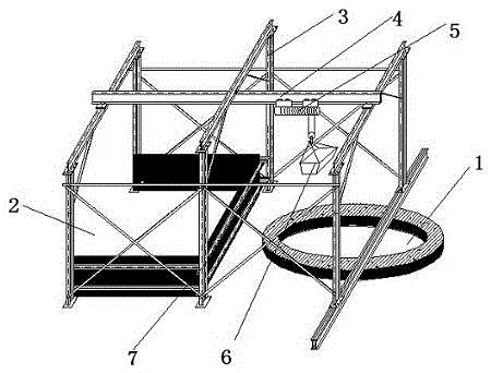
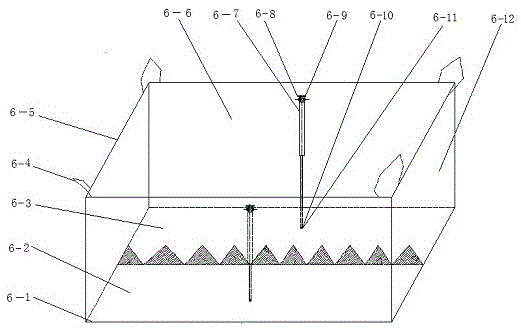
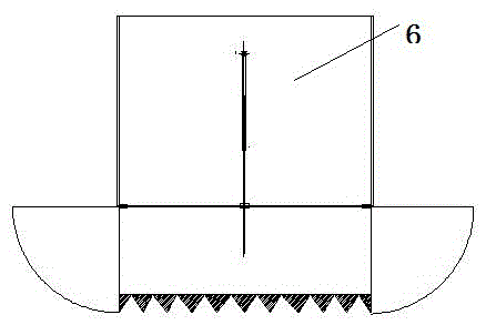
[0018] In the figure, a lifting and loading and unloading device for digging holes in an underground pipe gallery shaft of the present invention includes a shaft 1, a discharge area 2, a support frame 3, a lifting and unloading beam 4, an electric hoist 5, a loading hopper 6, and a living hinge 6 -1, hopper left bottom plate 6-2, hopper right bottom plate 6-3, hopper lifting lug 6-4, hopper short side side plate 6-5, hopper long side side plate 6-6, automatic telescopic oil cylinder 6-7, oil cylinder Upper fixed ear plate 6-8, oil cylinder connecting pin 6-9, oil cylinder lower connecting ear plate 6-10, oil cylinder lower connecting pin 6-11, hopper short side plate 6-12, baffle plate 7.

[0019] A lifting and unloading device for digging holes in an underground pipe gallery shaft, the lifting and unloading device includes a shaft 1, a discharge area 2, a support frame 3, a lifting and unloading beam 4, an electric hoist 5, and a loading hopper 6; the shaft 1 A support frame ...

Embodiment 2

[0026] The top of the shaft 1 is provided with a support frame 3, and the top of the support frame 3 is provided with two horizontal lifting and unloading beams 4, and the lifting and unloading beams 4 are all provided with an electric hoist 5, and the electric hoist 5 is connected with the loading hopper 6 through a wire rope; the support frame 3 is provided with a discharge area 2 isolated from the shaft 1; two horizontal beams 4 for lifting and unloading, one for lifting and the other for discharging, work interactively and cooperatively to improve construction efficiency. Progress, other with embodiment one.


PUM


Abstract

The invention discloses a lifting, conveying, loading and unloading device for hole digging of underground pipe gallery vertical shaft. The lifting, conveying, loading and unloading device comprises the vertical shaft, an unloading area, supporting frames, a lifting, conveying and unloading cross beam, an electric hoist and a loading hopper. The supporting frames are arranged on the upper portion of the vertical shaft. The lifting, conveying and unloading cross beam is arranged on the tops of the supporting frames. The electric hoist is arranged on the lifting, conveying and unloading cross beam and connected with the loading hopper through a steel wire rope. The unloading area isolated from the vertical shaft is arranged on the supporting frames. The lifting, conveying, loading and unloading device for hole digging of the underground pipe gallery vertical shaft has the advantages that the problem of earthwork outward transporting during excavating of an urban underground pipe gallery tunnel is solved, the difficult problem that a loading machine is needed to cooperate with a transporting car to load during loading and unloading of earthwork previously is solved through perpendicular and horizontal movement of the monorail electric hoist, the device is especially suitable for excavating of the urban tunnel and a subway with narrow construction fields, and investment is reduced.

Description

technical field [0001] The invention relates to a construction machinery tool, in particular to a device for digging, lifting, and unloading a vertical shaft of an underground pipe corridor. Background technique [0002] The urban underground comprehensive utility corridor is an underground space that integrates various municipal pipelines such as telecommunications, tap water, heat, gas, and electricity. The comprehensive utility corridor has realized the unified planning, construction and management of municipal construction, and the underground space has also been comprehensively and effectively utilized. [0003] Whether it is an underground pipe gallery project or a subway project, the excavation of underground tunnels is required, and the vertical transportation of underground soil is essential. However, most of the current vertical soil transportation methods use gantry crane or derrick transportation. These methods have many disadvantages: 1. The loader is required...

Claims


Application Information

Patent Timeline
IPC IPC(8): B66C19/00E02F7/00
CPCB66C19/00E02F7/00
Inventor 丁效武丁志文
Owner CHINA MCC17 GRP
Why Eureka
Try Eureka