Navigation signal capturing to tracking method and system

A navigation signal and signal technology, which is applied in the field of satellite navigation applications, can solve the problems that the tracking loop cannot successfully track the signal, the carrier frequency and the pseudo-code phase capture results are inconsistent, etc., and achieve the effect of shortening the capture and tracking time and broad application prospects

Inactive Publication Date: 2016-04-27
SPACE STAR TECH CO LTD
View PDF3 Cites 7 Cited by
  • Summary
  • Abstract
  • Description
  • Claims
  • Application Information

AI Technical Summary

Problems solved by technology

[0005] The purpose of the present invention is to provide a navigation signal-to-tracking code capture method and system to solve the problem in the prior art that when the capture result is directly brough

Method used


Image

  • Navigation signal capturing to tracking method and system
  • Navigation signal capturing to tracking method and system
  • Navigation signal capturing to tracking method and system

Examples


Example Embodiment

[0062] Embodiment two:

[0063] On the basis of the method provided in Embodiment 1, this embodiment combines specific engineering implementation cases to give specific technical implementation methods.

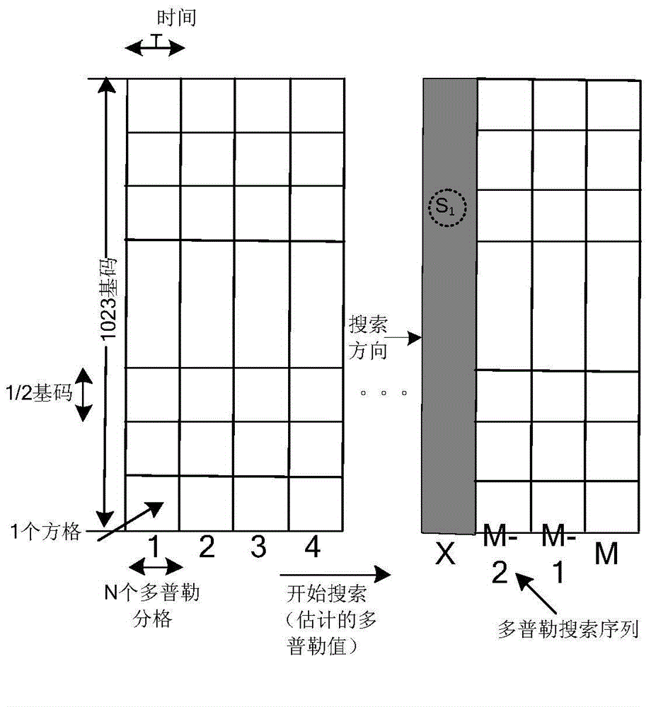
[0064] image 3 The principle diagram of fast acquisition of navigation signals and trans-tracking code phase compensation for GPS receivers. The method is parallel search in code domain and serial search in frequency domain, that is, the code phase parallel processing is used to complete a search of 1023 chips at a time. Swipe signal search frequency.

[0065] image 3 The horizontal axis is the frequency axis, and the vertical axis is the code axis. The code phase is searched in parallel, and the entire code phase domain is searched for each search. In the frequency domain, a serial search is adopted, one Doppler frequency point is searched at a time, and N Doppler frequency points are searched every time T. A total of M groups are searched, and the total number of search freque...

Example Embodiment

[0100] Embodiment three:

[0101] Corresponding to the methods provided in the first and second embodiments, this embodiment also provides a navigation signal transcoding acquisition system, see Image 6 The schematic diagram of the system architecture includes:

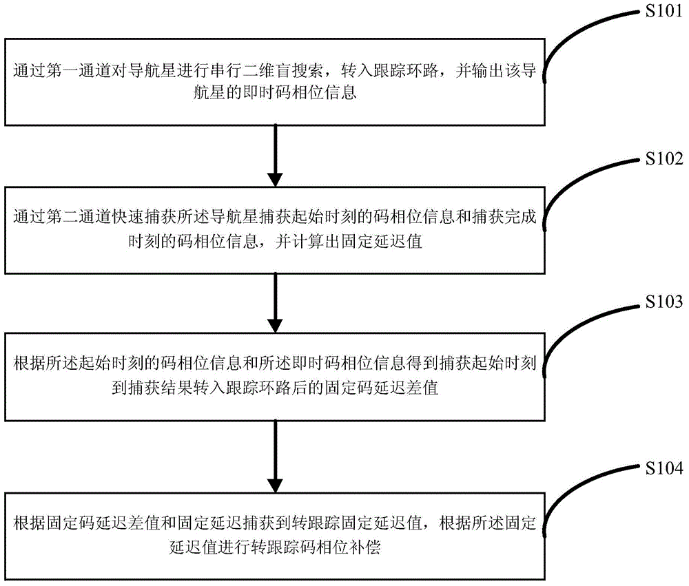
[0102] The real-time code phase information acquisition module 601 is used to perform a serial two-dimensional blind search on the navigation star through the first channel, enter the tracking loop, and output the real-time code phase information of the navigation star;

[0103] The fixed delay value acquisition module 602 is configured to quickly acquire the code phase information at the start time of the navigation star acquisition and the code phase information at the completion time of the acquisition through the second channel, and calculate a fixed delay value;

[0104] The fixed code delay difference acquisition module 603 is configured to obtain the fixed code delay difference from the capture start time to the time t...


PUM


Abstract

The invention relates to a navigation signal capturing to tracking method and system. The method comprises that serial 2D blind searching is carried out on a navigational star via a first channel, a tracking loop is turned to, and instant code phase information of the navigational start is output; code phase information in the capturing start time and code phase information in the capturing complete end time of the navigational star are rapidly captured via a second channel, and a fixed delay value is calculated; a fixed code delay difference from the capture start time to time when a capturing result is turned to the tracking loop is obtained according to the code phase information in the capturing start time and the instant code phase information; and a to-tracking fixed delay value is captured according to the fixed code delay difference and the fixed delay, and to-tracking code phase compensation is carried out according to the fixed delay value. According to the scheme, the fixed delay value is calculated accurately, a capturing code phase result is output in a compensated manner, and the method and system can be applied to accurate satellite object tracking. According to a real-time code phase deviant calculation method, the code phase deviant is compensated accurately, and the navigation signal capturing and tracking time can be shortened.

Description

technical field [0001] The invention belongs to the field of satellite navigation applications, and in particular relates to a method and system for capturing navigation signals converted to tracking codes. Background technique [0002] The returner and the service module of the third phase of the lunar exploration are separated at an orbital altitude of 5000km. After the returner and the service module are separated, the GPS receiver of the returner is turned on for fast navigation and positioning applications. The receiver positioning time needs to be less than 60s. The navigation application scenario and the requirement of fast positioning pose challenges to the navigation application of the GPS receiver: First, the navigation signal is dynamic. The returner of the third phase of the lunar exploration will re-enter and return to the earth at a high speed close to the second cosmic speed (11.2km / s), which will produce a large Doppler dynamic range (108kHz). time, affectin...

Claims


Application Information

Patent Timeline
IPC IPC(8): G01S19/30
Inventor 高阳王猛王元磊李兴国史雨薇王杰刘蕾董娟娟王晓杰
Owner SPACE STAR TECH CO LTD
Why Eureka
Try Eureka