Hybrid light field imaging system

A light field imaging and hybrid technology, which is used in stereo systems, components of TV systems, image communication, etc., to achieve the effect of convenient selection and use, and wide application prospects.

Active Publication Date: 2015-04-22
UNIV OF SHANGHAI FOR SCI & TECH
View PDF7 Cites 28 Cited by
  • Summary
  • Abstract
  • Description
  • Claims
  • Application Information

AI Technical Summary

Problems solved by technology

[0009] The present invention aims at the problem that current light field cameras cannot directly obtain images that users can watch. In the case of

Method used


Image

  • Hybrid light field imaging system
  • Hybrid light field imaging system
  • Hybrid light field imaging system

Examples


Embodiment Construction

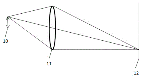
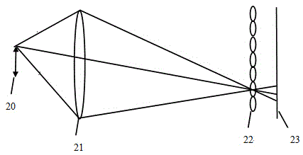
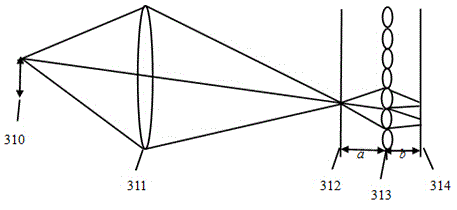
[0024] As shown in Figure 5, it is a schematic structural diagram of the hybrid light field imaging system of the present invention. The variable focus microlens array is composed of a plurality of identical microlenses or microlens groups arranged in a square or hexagonal array. Lens arrays at focal powers of 0 and specified values φ change between. When the lens focal length of the variable focus microlens array is infinity, that is, when the focal power is 0, such as Figure 5(a) As shown, the system works in the non-light field imaging mode (that is, the two-dimensional imaging mode), and ordinary two-dimensional images can be obtained. In this mode, the variable-focus microlens array 512 is equivalent to a parallel plate, which is equivalent to adding a plate element to the imaging optical path of a common digital camera. The object plane 510 is imaged on the image sensor 513 after passing through the main lens 511 and the flat plate element 512 to obtain a common two-...


PUM


Abstract

The invention relates to a hybrid light field imaging system. After being focused through a main lens, an object plane is imaged on an image sensor through a variable-focus microlens array, the object plane, the main lens, the variable-focus microlens array and the image sensor are sequentially placed on the same horizontal axis, the distance from the variable-focus microlens array to the main lens and the image sensor is kept unchanged all the time, and when focal power of the variable-focus microlens array is zero, the system obtains a common two-dimensional image; when the focal power of the variable-focus microlens array is changed from zero to phi, and namely, the focal length f ' of the variable-focus microlens array is equal to 1/phi, the system obtains a four-dimensional light field image. By changing the focal power of the variable-focus microlens array, the two-dimensional light field image and the four-dimensional light field image can be switched at will. Compared with a common light field camera, under the circumstance of not increasing the structural complexity of the system, the mode of light field imaging and the mode of common two-dimensional imaging can be achieved at the same time, and a user can select and use the imaging system conveniently.

Description

technical field [0001] The invention relates to an imaging technology, in particular to a hybrid light field imaging system, which can realize common two-dimensional imaging and four-dimensional light field imaging at the same time. Background technique [0002] Traditional digital camera structure such as figure 1 As shown, 10 is the object plane, 11 is the system lens, the light reaches the image sensor 12 after passing through the optical system, and the final picture is obtained through photoelectric conversion. The imaging process of traditional cameras adopts a two-dimensional projection method for three-dimensional space scenes, and only accumulates the intensity of light on the detector pixels, that is to say, only considers the spatial distribution of objects on the image plane, and loses The information in the direction of propagation of the light is limited, which limits the reshaping of the image. [0003] Light field imaging not only collects the spatial infor...

Claims


Application Information

Patent Timeline
IPC IPC(8): H04N5/225H04N5/232H04N13/02
Inventor 张薇郭鑫速晋辉
Owner UNIV OF SHANGHAI FOR SCI & TECH
Why Eureka
Try Eureka