A conductive foam positioning die-cutting device

A technology of conductive foam and positioning mold, which is applied in cleaning methods and appliances, chemical instruments and methods, and cleaning methods using gas flow, etc., which can solve the problems of affecting the flatness of the incision, sticking dust, and unevenness of the cut. Achieve the effects of reducing dust adhesion, improving work efficiency and maintaining flatness

Active Publication Date: 2022-04-01
玉锡科技(苏州)有限公司
View PDF9 Cites 1 Cited by
  • Summary
  • Abstract
  • Description
  • Claims
  • Application Information

AI Technical Summary

Problems solved by technology

[0003] Conductive foam is cut according to the required length before use and then spliced ​​later. At present, in the production process, the operator usually uses scissors or a cutter to cut the conductive foam and then splice it. The disadvantages of this cutting method are: It is easy to have uneven cuts during cutting, and gaps are easy to appear between the two sections of conductive foam after splicing. At the same time, if the conductive foam is wrinkled or uneven before cutting, it will directly affect the cut flatness after cutting. Manually The cutting operation is also easy to make the incision of the conductive foam stick to dust, which will affect the product quality and subsequent use and connection

Method used


Image

  • A conductive foam positioning die-cutting device
  • A conductive foam positioning die-cutting device
  • A conductive foam positioning die-cutting device

Examples


Embodiment Construction

[0027] Specific embodiments of the present invention will be described below in conjunction with the accompanying drawings.

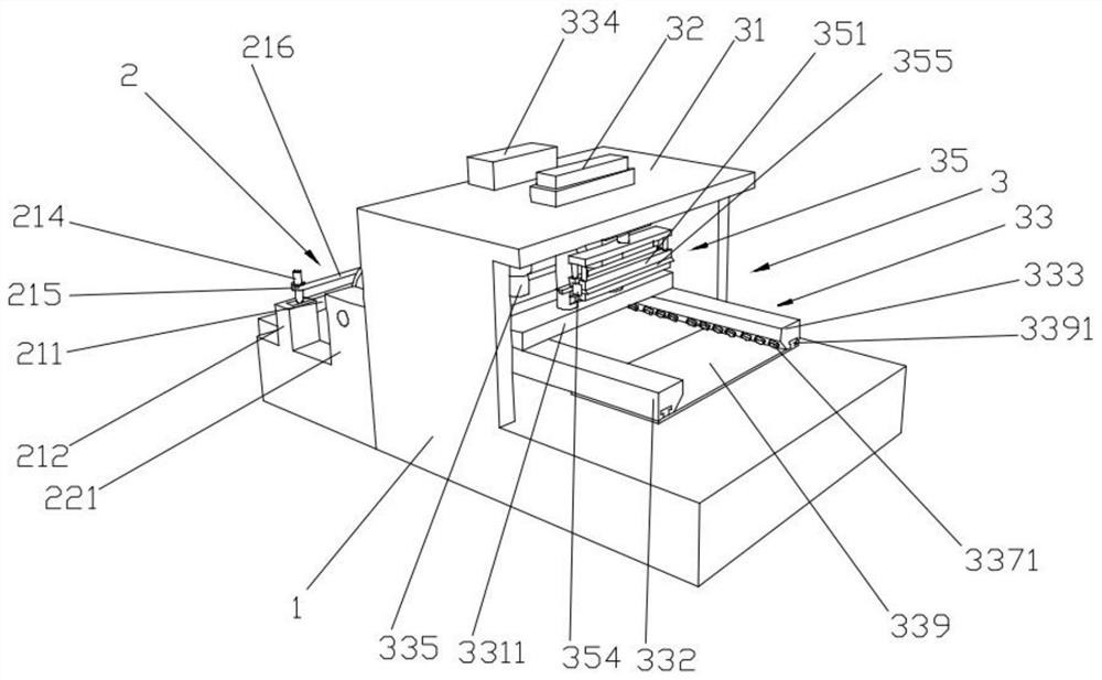
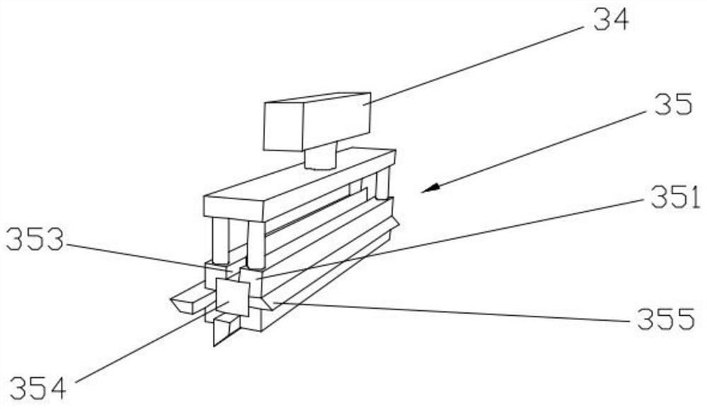
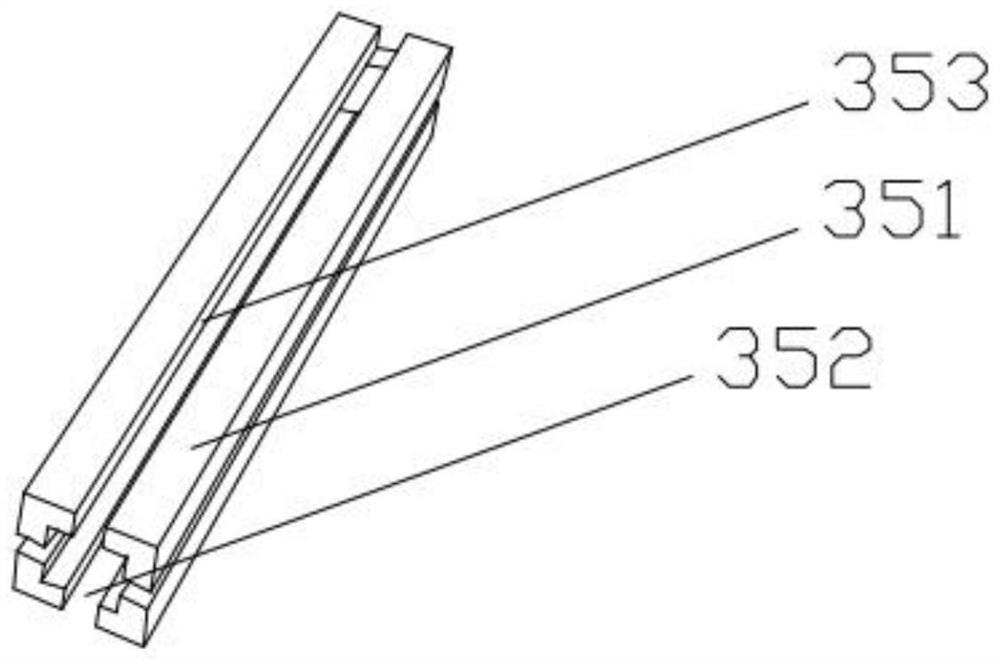
[0028] Such as Figure 1-7 As shown, it is a conductive foam positioning die-cutting device of this embodiment, which includes a die-cutting frame 1, and a feeding leveling device 2 and a cutting device 3 are arranged side by side on the top surface of the die-cutting frame 1. The feeding leveling device 2 includes a limit feed rod device 21 and a feed roller device 22, the limit feed rod device 21 and the feed roller device 22 are arranged side by side on the top surface of the die-cutting frame 1 in sequence, and the limit feed rod device 21 includes a limit Rod body 211, the two ends of limit rod body 211 are all provided with limit bar seat 212, and limit bar seat 212 is fixedly arranged on the top surface of die-cutting frame 1, and the side wall of limit bar seat 212 is all provided with limit bar Adjustment groove 213, both ends of the limit rod...


PUM


Abstract

The invention provides a conductive foam positioning die-cutting device, which relates to the technical field of conductive foam processing equipment, and includes a die-cutting frame. A feeding leveling device and a cutting device are arranged side by side on the top surface of the die-cutting frame. It includes a limit feed rod device and a feed roller device, the limit feed rod device and the feed roller device are arranged side by side on the top surface of the die-cutting frame in sequence, the limit feed rod device includes a limit rod body, and the two sides of the limit rod body Both ends are provided with a limit rod seat, and the limit rod seat is fixed on the top surface of the die-cutting frame, and the limit rod seat is provided with a limit rod adjustment groove on the side wall, and both ends of the limit rod body are slidingly arranged on the In the limit rod adjustment groove, both ends of the limit rod body are also movably provided with adjustment screws, and one end of the adjustment screw rod moves through the limit rod body and is threadedly connected with the bottom surface of the limit rod adjustment groove. The invention has the advantages of improving the flatness of the incision and avoiding dust from adhering to the incision.

Description

technical field [0001] The invention relates to the technical field of conductive foam processing equipment, in particular to a positioning die-cutting device for conductive foam. Background technique [0002] Conductive foam, that is, wrapping conductive cloth on the flame-retardant sponge, after a series of treatments, it has good surface conductivity, and can be easily fixed on the device to be shielded with adhesive tape. When encountering radio waves, it will According to the nature of the object, it can reflect, absorb, and provide excellent shielding effect. It is widely used in PDP TV, LCD monitor, LCD TV, mobile phone, notebook computer, MP3, communication cabinet, medical equipment and other electronic products as well as military and aerospace fields. . [0003] Conductive foam is cut according to the required length before use and then spliced ​​later. At present, in the production process, the operator usually uses scissors or a cutter to cut the conductive foa...

Claims


Application Information

Patent Timeline
Patent Type & Authority Patents(China)
IPC IPC(8): B26F1/44B26F1/38B26D5/12B26D7/02B26D7/06B26D7/08B26D7/18B26D7/26B08B5/02
CPCB26F1/44B26F1/38B26D5/12B26D7/02B26D7/0608B26D7/06B26D7/08B26D7/088B26D7/1863B26D7/2614B08B5/02
Inventor 李海趁袁昊
Owner 玉锡科技(苏州)有限公司
Why Eureka
Try Eureka