
Vehicle body structure

A body and structure technology, applied in the field of lower body structure, can solve the problems of inability to pass and join the inner parts of the center pillar, and achieve the effects of ensuring rigidity and strength, improving rigidity and strength, and improving productivity and yield.

Active Publication Date: 2016-04-27
HONDA MOTOR CO LTD
View PDF6 Cites 10 Cited by
  • Summary
  • Abstract
  • Description
  • Claims
  • Application Information

AI Technical Summary

Problems solved by technology

[0014] In addition, in the vehicle body structure described in Patent Document 2, there is a problem that, unlike the vehicle body structure described in Patent Document 1, the lower end of the center pillar inner member cannot be separated from the side sill in order to arrange the bulkhead 17 in the cross-section of the side sill. Pass through and join in section

Method used


Image

  • Vehicle body structure
  • Vehicle body structure
  • Vehicle body structure

Examples


Embodiment Construction

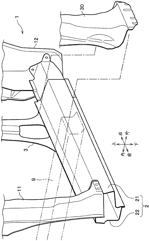
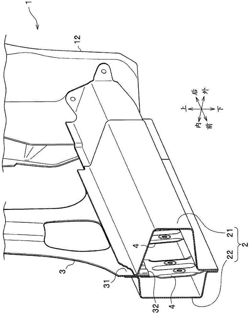
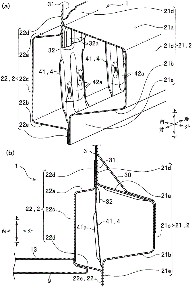
[0052] properly refer to Figure 1 to Figure 5 A vehicle body structure 1 of a vehicle (not shown) according to the first embodiment of the present invention will be described in detail. In addition, the type of vehicle is not particularly limited. For convenience of description, the direction of the vehicle is referred to as the front-rear direction, the up-down direction, and the vehicle width direction (left-right direction). .

[0053] figure 1 It is a perspective view of the left side of the vehicle body viewed from the front outer side, and shows the structure of the vehicle body from the front pillar 11 to the rear wheel house 12 .

[0054] Such as figure 1 As shown, the vehicle body structure 1 according to the first embodiment of the present invention includes: a side sill 2 extending in the front-rear direction on the side of the vehicle body; Square extension column; extension 4 (refer to figure 2 ) that is joined to the lower end of the center pillar inner me...


PUM


Abstract

A side sill (2) is configured, in a closed section, from a side sill outer element (21) comprising an outer upper wall, outer lower wall, an outer side wall, an outer upper flange and an outer lower flange, and from a side sill inner element (22) comprising an inner upper wall, an inner lower wall, an inner side wall, an inner upper flange and an inner lower flange. On the lower end, a pillar (3) has a joint portion (31) which is held between and joined to the outer upper flange (21d) and the inner upper flange (22d), and a first extension part (32) and a second extension part (33) which extend from the joint portion (31) into the closed section of the side sill, and is provided with an extension (41, 42), the top end of which is joined to the first extension part (32) and / or the second extension part (33) and the bottom end of which is held between and joined to the outer lower flange (21e) and the inner lower flange (22e). By means of this configuration, it is possible to ensure a suitable rigidity through the minimally necessary weight increase, depending on the vehicle specifications.

Description

technical field [0001] The present invention relates to a vehicle body structure, and more particularly, to an underbody structure including a junction between a side sill and a pillar. Background technique [0002] Recently, in order to comprehensively improve driving performance, riding performance, fuel consumption performance, etc., vehicle body rigidity and weight reduction are required for vehicles. In addition, since the vehicle body structure requires different body rigidity, strength, and the like depending on vehicle specifications and destinations, various changes are required to suit the vehicle specifications and the like. [0003] Conventionally, as a means of increasing the rigidity of the side sill of the vehicle body, a vehicle body structure is known in which an extension is arranged in the front-rear direction of the vehicle body so as to partition the inside of the side sill (for example, refer to Patent Document 1); A partition is arranged inside so as ...

Claims


Application Information

Patent Timeline
IPC IPC(8): B62D25/20B62D25/04
CPCB62D25/025B62D25/04B62D25/2036
Inventor 江村雅彦
Owner HONDA MOTOR CO LTD
Learn More