

Insulation board machining device and method
A processing device and insulation board technology, which is applied to the device and coating of the surface coating liquid, to achieve the effects of avoiding waste, improving productivity, and increasing processing speed
- Summary
- Abstract
- Description
- Claims
- Application Information
AI Technical Summary
Problems solved by technology
Method used
Image

Examples
Embodiment approach 1
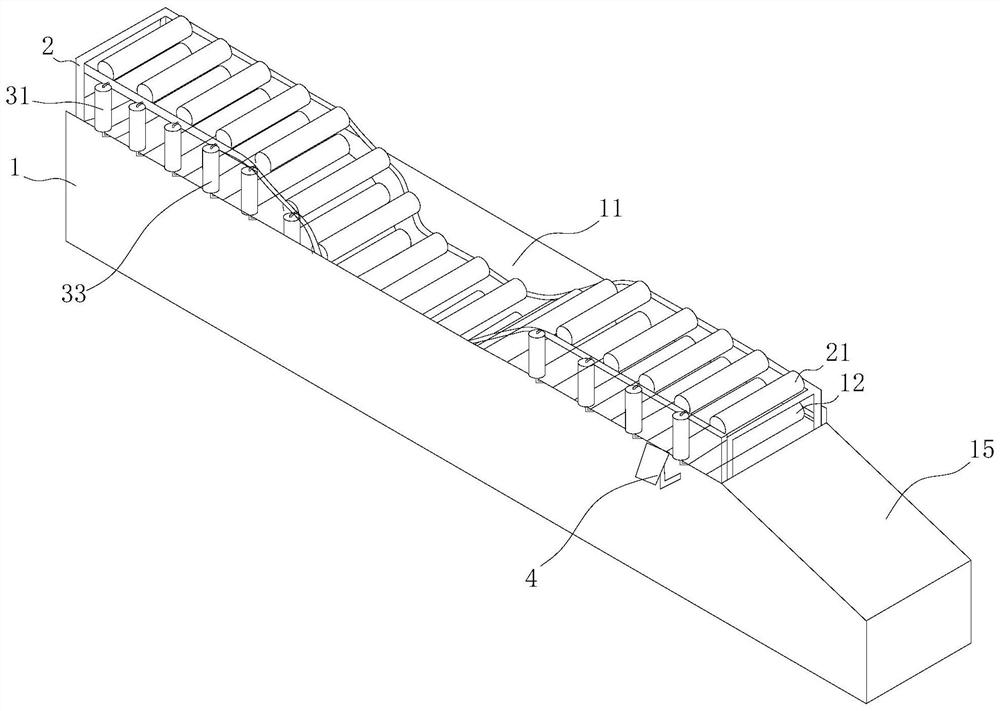
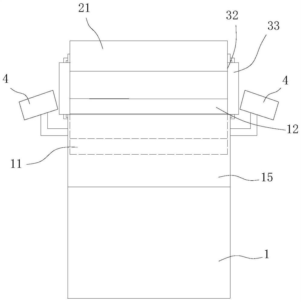
[0050] Embodiment 1: In this embodiment, the distance between two adjacent second rollers 21 is smaller than the length of the insulation board, and they are arranged corresponding to the first rollers 12 in the vertical direction. The insulation board is always clamped by two groups of rollers during the moving process, which increases the transmission efficiency of the first roller 12 and the second roller 21, and has a greater clamping force on the insulation board, preventing The insulation board is offset from the material feeding channel 3 .
[0051] Of course, the second roller 21 may also be arranged at a distance from the first roller 12 in the vertical direction, which is not specifically limited here.
Embodiment approach 2
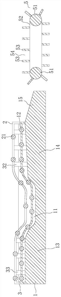
[0052] Embodiment 2: In this embodiment, if figure 2 As shown, the distance between two adjacent second rollers 21 is greater than the length of the heat preservation board, so that the heat preservation board is always subjected to two first rollers 12 and one second roller 12 during its movement. The clamping of the column 21 reduces the number of the second rollers 21 on the basis of ensuring the transmission efficiency, simplifies the structure of the processing device, and reduces the cost.
[0053] Of course, the distance between two adjacent second rollers 21 may also be equal to the length of the insulation board, which can still maintain the transmission efficiency and reduce the cost, which is not specifically limited here.
[0054] As a preferred embodiment of this application, such as figure 2 As shown, the slurry tank 11 divides the machine body 1 into a feeding area 13 and a processing area 14, and the height of the feeding channel 3 above the feeding area 13 ...
Embodiment 1
[0077] Embodiment 1: In this embodiment, the limiting member is a baffle arranged along the length direction of the body 1, and the baffle extends upward so that the side of the baffle constitutes the abutting surface, Form a resisting effect on the heat preservation board, restrict the heat preservation board from deviating from the material conveying channel 3, and the baffle is integrally formed with the body 1, so as to save the assembly process and facilitate manufacturing.
PUM
 Abstract
Description
Claims
Application Information